Modeling Features

You can modify a feature using the control point modification command without losing the feature properties. ^


Before you begin:
  • You must have access to the ICEM Shape Morphing or ICEM Shape Design for Aero app.
  • Open a 3D shape containing two curves between which can be created a blend curve.
See Also
About Feature Modeling
Creating Blend Curves
Using Control Points
  1. Create a blend curve between two 3D-Curves using the Blend Curve command.
  2. From the Modification section of the action bar, click Feature Modeling .
  3. Select the blend curve.
  4. In the Feature Modeling dialog box, change to the Modification tab.
    For Feature Modeling, the options of the Control Points command are available.
  5. Select the Robot plane option and modify the middle control point.

    Depending on the selected feature, the control point modification possibilities can be restricted to respect the constraints of the original element, e. g. continuities.

    The Blend Curve.1 in the example has been created with G2 continuity and an order of 6. In this case, the control points can only be moved along the control point mesh to respect the G2 continuity.
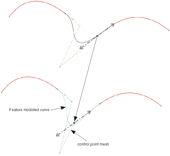
  6. Click OK.
    A new element Feature Modeling.1 is created and the input feature Blend Curve.1 is automatically set to No Show mode.

  7. In the work area, double-click the Feature Modeling.1 element.
    The Feature Modeling dialog box opens with the current settings.
  8. Modify again control points and close the dialog box with Cancel.
    The element Feature Modeling.1 is reset to the previous shape.