-
From the Operations section of the action bar, click Create 3D Grid Skeleton
 . .
The 3D Grid Skeleton panel appears.
-
In the Name box, enter a name for the grid you want to create (for example Grid Skeleton).
The grid will be identified by this name in the tree.
-
In the Mode list, select Relative or Absolute to define the grid construction mode.
In the relative mode, grid planes are positioned with respect to each other. Moving a plane impacts other planes offset from that plane. This is the default mode. In the absolute mode, grid planes are positioned with respect to the grid origin. Planes can be repositioned independently of one another.
-
Under the Origin area,
enter absolute coordinates.
You can select a point in the 3D area to define the grid origin.
If you select a point, the point is identified in the panel. The grid origin is now linked to this point. Note:
If the input values for the origin of 3D grid are not defined, the three planes (XY, YZ, and ZX) of its part are used to set it.
-
Optional:
Under the First direction in XY plane area,
do either of the following:
-
In the Cartesian tab, enter H and V coordinates to define the local x-axis.
- In the Polar tab, enter an angle to define the polar axis.
- Select a line in the 3D area.
Note:
By default, the local x-axis is positioned along the absolute x-axis.If you select a line, the line is identified in the panel. The first direction is now linked to this line.
-
To specify grid coordinates, do either of the following:
- Select Cartesian, and specify the distance between grid points and number of points along x, y and z axes.
- Select Polar, and specify the radius, amplitude, spacing along the z-axis, and the number of grid points in each case.
Note:
You can expand other coordinate sets to enter up to three more different combinations to define your grid.
- Click OK to create the grid.
The grid is created and is identified in the tree. 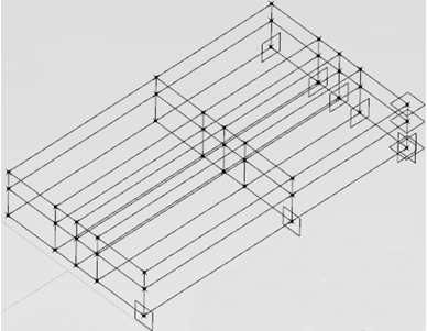 Note:
Grid places are
associative. Moving a plane updates the grid, which is useful when modifying a structure
(for example, moving a plane). To see the defined structure in the updated grid,
double-click the root product in the tree. The following options must be set in the :
- Keep link with selected object
- Synchronize all external references when updating the 3D
shape
- Optional: To edit the 3D grid skeleton, do either of the following:
- Double-click the 3D grid skeleton node in the tree.
- Select the 3D grid skeleton in the 3D area and click Create 3D Grid Skeleton from the action bar.
Notes:
- You can edit only grid coordinates (points).
- You cannot edit a 3D grid skeleton created using the old 3D Grid Skeleton command of the Steel Outfitting Design app.
|
 > Preferences: