Add Mate Using Context Toolbar
You can add mate between assembly components to constrain them relative to each other.
-
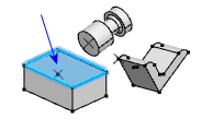
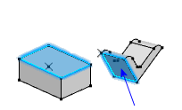
In the 3D area, click 'ctrl + geometry' (such as a
face, edge, or vertex) from each of the components to mate.
The context toolbar displays all mate types that are valid
for the selected items. 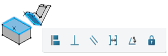
-
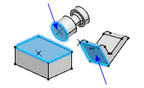
Click a mate type to preview the mate.
For example, click Coincident
 . .
The components move to a position that satisfies the mate. 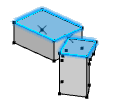 In the dialog box, you can click other mate types to preview.
- Optional:
Specify other options in the dialog box.
| Option | Description |
|---|
 |
Flip. Flips the alignment of the
components. Available for mate types that have two possible
alignments, such as coincident, distance, parallel, and
tangent. |
| |
Distance. Sets the value for a distance
mate. |

|
Reverse. Reverses the direction of the
distance dimension. |
| |
Angle. Sets the value for an angle
mate. |
For example, click Flip
.
The bracket alignment flips but the selected faces remain
coincident. 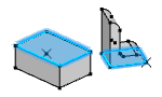
-
Click Apply and Continue.
The mate is added and is listed under Mate in the
Design Manager
tree. 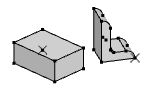
Note:
The empty dialog box remains open to create more mates. Renaming Mate: You can rename
the mate by, a slow double-click the name of the created mate, in
the Design Manager tree.
Add Multiple Mate in a Single Operation
You can mate multiple components to a common reference in a single operation.
-
In the 3D area, select the geometry to which you want
to mate several other components.
-
Click 'ctrl + geometry' on other components to mate.
The components move to a position that satisfies the mate. In the dialog box, you
can select options and click other mate types to preview. 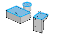
-
Click Apply and Continue.
Adds a mate between the first component and each of the other selected components.
In this example, two mates are added in the model and listed separately
under Mate in the Design Manager
tree. 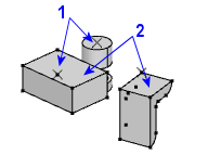 Note:
The empty dialog box remains open to create more mates. Renaming Mate: You can rename the
mate by, a slow double-click the name of the created mate, in the
Design Manager tree.
Add Mate from the Action Bar
You can add mate between assembly components to constrain them relative to each other.
-
Click the Mate
 from the Assembly section of action bar.
The Mate dialog box appears.
-
In the 3D area, click the geometry (such as a face,
edge, or vertex) from each of the components to mate.
 |
| You can see the selected components in the Mate dialog
box. |
|
| The
Mate
dialog box displays all mate types that are valid for
the selected items. |
Note:
The Mate
from the Assembly section of action bar allows you to select only two
geometries to mate at a time. When more than two geometries are selected
the last two selections are considered to mate.
-
Click a mate type to preview the mate.
For example, click Coincident
.
The components move to a position that satisfies the mate. In the dialog box, you can click other Mate types to
preview. - Optional:
Specify other options in the dialog box.
| Option | Description |
|---|
|
|
Flip. Flips the alignment of the
components. Available for mate types that have two possible
alignments, such as coincident, distance, parallel, and
tangent. |
| |
Distance. Sets the value for a distance
mate. |
|
Reverse. Reverses the direction of the
distance dimension. |
| |
Angle. Sets the value for an angle
mate. |
For example, click Flip
.
The bracket alignment flips but the selected faces remain
coincident.
-
Click Apply and Continue.
The mate is added and is listed under Mate in the
Design Manager
tree. Note:
The empty dialog box remains open to create more mates. Renaming Mate: You can rename the
mate by, a slow double-click the name of the created mate, in the
Design Manager tree.
|