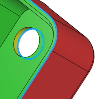
Parting Line | |||
| |||
-
From the Mold Features section of the action bar, click
Parting Line
 .
.
-
In the dialog box, select the pulling direction from the work area. This
automatically adds parting lines and edges to the dialog box.

- Select other edges from the work area as parting lines.
- Enable split silhouette if required. The split silhouette works on the straddle faces and converts them to a combination of positive and negative faces.
-
You can choose the colors for the faces from the color palette. Double-click the draft
color to open the color palette. The default colors for faces are as below:
Option Description Faces Default Colors Positive faces 
Straddle faces 
Verticle faces 
Negative faces 

- Optional:
From the Advanced section, you can enable Display
curve endpoints to display any selected open parting lines
Note: If you manually define Parting Line, the software indicated incomplete edges as dots (marked in orange circles here).

- Optional:
From the Advanced section, enable
- Remove open edge selections
- Remove unnecessary loops
- Undo last change
-
Click
 .
.
 Note: To edit parting lines, double-click the parting line in the Design Manager tree.