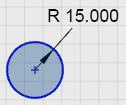
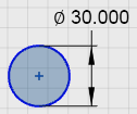
Dimensioning a Sketch

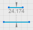
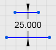
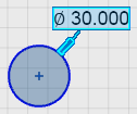
You can constrain sketch entities by dimensioning their length, width, or diameter. You can dimension the distance or angle between sketch entities or between a sketch entity and an external item such as a model edge. A geometry length of "0" is not permitted.

This task shows you how to:

Dimensions as you Sketch

You can enter the dimension value as you sketch.

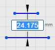
  1. Start sketching an entity. The Dimension Edit Box is displayed as you sketch.

    A Rectangle entity is used in this example. The other sketch entities behave similarly.
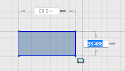


  2. Type the value for the dimension and press Enter.

    Press Tab to switch between the dimensions, in case the sketch entity has more than one dimension.
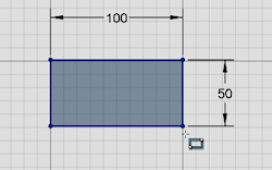
  3. Optional:

    • When you press Enter twice the curve completes or you move to the next step.
    • When you enter the dimension value of any sketch entity, you can snap this entity horizontally or vertically only.

  4. Click .

Add a Dimension to an Existing Sketch

You can add dimensions to a sketch.

  1. Select one sketch entity or Ctrl + select two sketch entities.
    A preview dimension appears.

  2. Click the preview dimension.


  3. Type a new value and press Enter.


    Note: Changing the first sketch, first dimension (radius, diameter) value of any linear, circular, and nonangular sketch entity in the work area scales an entire sketch according to the new value.

  4. Optional: When you dimension your sketch, you can do the following:
    • Edit the value by clicking the number.
    • Provide numeric values as an input. You can add an equation or perform the basic operations such as bracket, addition, subtraction, multiplication, and division on these values.
      Note: If you provide numeric input values along with their units, the system converts the input values to the default unit set in the application. You can provide input values having following length, angle, and metric units:

      Length unit

      Angle unit

      Metric unit

      m (Meter)

      in (Inch)

      ft(Foot)

      yd (Yard)

      mi (Mile)

      Angstrom

      Mil (thousand of an inch)

      li (Link - 66/100 of a foot)

      rd (Rod - 16th1/2 feet)

      ch (Chain - 66 feet, 22 yards, 100 links or 4 rods)

      rad (Radian)

      deg (Degree)

      grad (Gradian)

      Cycle

      arcsec (Arcsecond)

      arcmin(Arcminute)

      da (Deca-1e1)

      h (Hecto-1e2)

      k (Kilo-1e3)

      M (Mega-1e6)

      G (Giga-1e9)

      T (Tera-1e12)

      P (Peta-1e15)

      E (Exa-1e18)

      Z (Zetta-1e21)

      Y (Yotta-1e24)

      d (Deci-1e-1)

      c (Centi-1e-2)

      m (Milli-1e-3)

      u (Micron-1e-6)

      n (Nano-1e-9)

      p (Pico-1e-12)

      f (Femto-1e-15)

      a (atto-1e-18)

      z (Zepto-1e-21)

      y (Yocto-1e-24)

    • Reposition the dimension by dragging any part of the dimension or by selecting the Reposition Dimension option from the context toolbar. You can then move the pointer and click to place the dimension.
    • Switch a dimension between driving and driven by selecting the Driving/Driven option from the context toolbar.

      • Driving dimension: When you change dimensions, it changes the geometry of the model.
      • Driven dimension: When you change the geometry of the model, it changes the dimensions. You can use driven dimension to only measure an existing model without actually changing the dimension value.

    Depending on the sketch entities you place on sketch area, following context toolbar options become available.

    Context toolbar option Name of the entity Description


    Linear This option becomes available when you click the edge of a linear entity.


    Angular This option becomes available when you click any nonparallel sketch entity.


    Circular This option becomes available when you click the edge of the circular entity.
    Tip: If you select two linear entities that are not parallel to each other, then both Angular and Linear are available. If you click Linear , the entities become parallel.

Switch Between Driving and Driven Dimensions

You can toggle dimensions between driving and driven. If you add a dimension that causes the sketch to be over defined, the over defining dimensions are displayed in red. Switch one of the dimensions to driven to correct the condition.

  1. Select an arrow or extension line of a dimension.
    For example, select an arrow or extension line of the 50.000 dimension.

  2. On the context toolbar, click Driving/Driven .
    The sketch is no longer over defined. The driven dimension is gray.

    Alternatively, you can use the Sketch Diagnostic tool to resolve the overdefined sketch.

Switch Between Radius and Diameter Dimensions

You can toggle a circular dimension between radius and diameter or make the dimension linear.

  1. Select the extension line of a diameter dimension.


  2. On the context toolbar, click Radius/Diameter .
    The dimension switches to a radius dimension.


    You can repeat the command to switch back to a diameter dimension.

  3. To change a radius or diameter dimension to a linear dimension:
    1. Select the extension line of the dimension.
    2. On the context toolbar, click Linear .
      The dimension becomes linear.