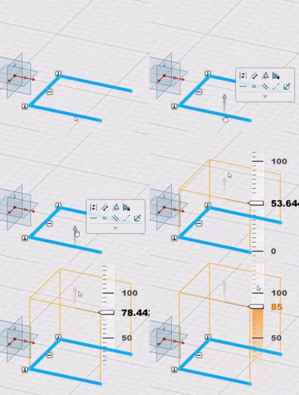
Create an Extrusion
-
From the Sheet Metal section of the action bar, click Extrusion
 .
.
-
In the dialog box, click Profile, and from the work area, select an open sketch as a profile.
Select an open sketch for extrusion.
- Click Fixed geometry, and from the work area, select an edge or point as a reference.
-
From the Sketch Orientation list, select one of the
following:
Option Description  Inside
Orients the sketch at the inside position of the wall thickness.  Middle
Orients the sketch at the middle position of the wall thickness.  Outside
Orients the sketch at the outside position of the wall thickness. -
For Direction 1 and Direction
2, specify the direction of an extrusion by selecting one of
the following:
Option Description Dimension Extrudes a selected profile on one direction. If Dimension is selected for Direction 1, select Symmetric for Direction 2.
Midplane Extrudes a selected profile on mid plane. If Midplane is selected for Direction 1, Length is equal to total length of extrusion.
Symmetric Extrudes a selected profile on two opposite directions. This option appears only if Dimension is selected for Direction 1. If the Symmetric option is selected for Distance 2, Length equals half of total length.
Up to plane Extrudes a selected profile up to the plane. Up to surface Extrudes a selected profile up to an existing surface. - Specify a Distance from the selected profile to create the extrusion.
- Optional:
Under Bends, select Automatic
Bend to specify the bend extremities for Relief
1 and Relief 2 using one of the
following options:
By default, Automatic Bend is selected.
Option Description Minimum with no relief The bend corresponds to the common area of the supporting walls along the bend axis, and shows no relief. Square relief The bend corresponds to the common area of the supporting walls along the bend axis, and a square relief is added to the bend extremity. Length 1 and Length 2 parameters can be modified. Round relief The bend corresponds to the common area of the supporting walls along the bend axis, and a round relief is added to the bend extremity. Length 1 and Length 2 parameters can be modified. Linear The unfolded bend is split by two planes going through the corresponding limit points (obtained by projection of the bend axis onto the edges of the supporting walls). Tangent The edges of the bend are tangent to the edges of the supporting walls. Maximum The bend is calculated between the furthest opposite edges of the supporting walls. Closed The bend corresponds to the intersection between the bends of the two supporting walls. The closed bend extremity lies on the surface of the bend. Flat joint The two bends are joined in a flat view. If you create a feature on the extruded profile, the bend extremities are recomputed to ensure a consistent result.
Linked to SheetMetal parameters
 shows that the given parameter is driven from global sheet metal
parameters. You can click to unlink it.
  shows that the given parameter is a local or custom value.
 - Under Custom bend calculation , click Bend geometry and from thework area, select a vertex.
-
For Bend calculation, specify a value for
K-factor.
You can create multiple K-factors for multiple bends.
Click Linked to SheetMetal parameters
 next to K factor to get the options, Bend
Allowance and Bend Deduction for
bend calculation. Specify the value for bend allowance or bend
deduction.
 -
Click
 to
save and exit.
Note: You can use equations for all numeric parameters in this feature. Click the dimension text. The dimension text becomes editable. Type = in the input field, to open the Equation dialog box and enter a formula or number. From the list, select a parameter. You can perform the basic operations such as addition, subtraction, multiplication, and division on the parameter value.


 .
.