Create Sheet Metal Wall from a Closed Ruled Surface
You can create sheet metal wall from a ruled surface.
- Open or import the model into the xSheetMetal application.
-
From the Sheet Metal section of the action bar, click Convert
Surface
 .
.
- From the Sheet Metal Parameters dialog box, enter the Sheet Metal parameters as required. You can change these parameters anytime from the Design Managertree or by clicking the Sheet Metal Parameters from the Sheet Metal tab on the action bar.
-
Click
 from the upper-right corner of the Sheet
Metal Parameters dialog box.
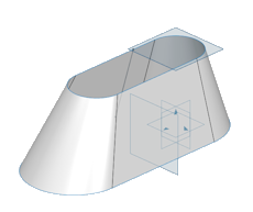
- In the Convert Surface dialog box, select the surface to be converted.
- From the dialog box, select the surface orientation, bottom, middle or top.
-
A reference wire and fixed point are automatically selected. To modify
them:
- Select a reference wire lying on the selected surface.
- Select a fixed point that lies both on the surface and on the reference wire.
- Optional:
Select a tear wire.
You can select the tear wire to determine where the Sheet Metal wall splits when flattened.
Important: The reference wire, the fixed point, and the tear wire, used to flatten the model, must lie on the surface. -
To offset the converted surface, enter a value in the
Offset box.
By default, the offset value is 0 mm.
 You can see the preview of the converted surface with the offset.
 -
Click
 .
.
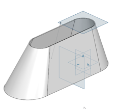
- Optional:
From the Sheet Metal section of the action bar, click Flat
Pattern
 to unfold the
model.
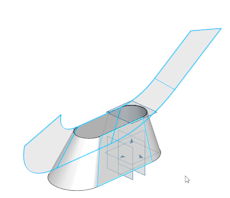 Note: The model is unfolded from the selected tear wire.
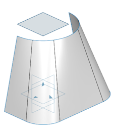
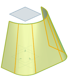 You can see the preview of the converted surface with the offset.

