Set the Prerequisite
-
Create a model using design features on the XY plane to use it as the punch
geometry. Save the model in a collaborative space.
Note:
The direction of a model is determined by the positive Z direction
with respect to the wall feature.
-
In the xSheetMetal
app, open a sheet metal part that contains
at least one wall feature.
-
From the Tools section of the action bar, click Insert Ordered Geometrical Set
 . .
A new container is added in the Design Manager Tree to hold the
punch geometry.
-
From the Feature section of the action bar, click Insert Geometry
 . .
-
In the Insert Geometry dialog box, click
Choose Component.
-
Select the punch geometry that you have saved in a collaborative space and
click
 . .
The geometry is inserted at the origin of a sheet metal model. The
Ordered Geometrical Set now holds this geometry in it.
-
In the Design Manager Tree, right-click the sheet metal feature and from
the context toolbar, click Activate.
-
In the work area, click a sheet metal face where you want to perform stamping.
-
From the context toolbar, click Create or Edit Sketch
 . .
-
Sketch a point on a sheet metal face to mark a location to create a stamp.
You can specify the dimensions for the point.
-
Click .
Create a User Stamp
-
From the Sheet Metal section of the action bar, click User Stamp
 . .
-
In the User Stamp dialog box, click stamp
position.
-
From the work area, select a sketch point that you have created earlier.
- Optional:
Click
 to reverse the side of sheet metal where you want to create a
stamp. to reverse the side of sheet metal where you want to create a
stamp.
-
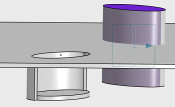
Click Punch, and from the work area, select the punch geometry for creating a stamp.
Alternatively, from the Design Manager tree, click Ordered Geometrical
Set and select the punch geometry.
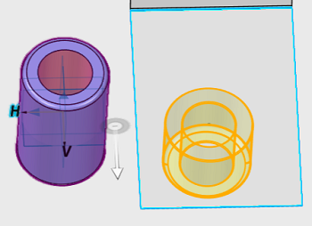 When you drag the handle, you can see the preview. Shaded preview
appears on the release of the handle. - Optional:
Select Both Sides check box to create stamping on
both sides of the wall.
- Optional:
Click the Use Fillet check box to create a fillet
at an intersection of a punching geometry and sheet metal wall.
- Optional:
Specify the Radius for a fillet.
- Optional:
Click Open faces, and from the work area select one or more faces from the original punch geometry that you want
to leave open for stamp creation.
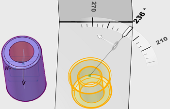
- Optional:
Click Rotation Reference, and from the work area select an edge to specify the direction to rotate the user stamp.
Note:
The default Rotation Reference is a horizontal axis from the stamp
position sketch.
- Optional:
Specify the Rotation angle.
-
Click .
| Result | Description |
|---|
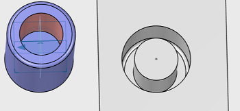 |
User stamp created on the wall |
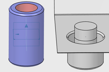 |
User stamp on both sides |
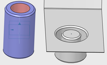 |
User stamp with fillet |
 |
User stamp with open face |
 |
Rotated user stamp |
Note:
You can use equations for all numeric parameters. Click the dimension text. The
dimension text becomes editable. Type = in the input
field, to open the Equation dialog box and enter a formula or number.
Select a parameter from the list. You can perform the basic operations
such as bracket, addition, subtraction, multiplication, and division on
the parameter value.
|
