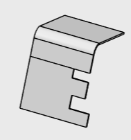
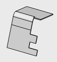
Create a Wall from Edge by Instant Drag
-
Select an edge of a wall.
-
Drag the arrow handle that appears.
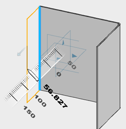
You can drag the on-screen handles to adjust the height, angle, and length of
the wall on an edge. A mini panel appears.  Optional:
- Click Material side to flip the material
side of the wall on edge.
- Click Reverse Direction
 to reverse the direction of the wall on an edge. to reverse the direction of the wall on an edge.
- Click Expand
 in the panel to expand the Wall on Edge dialog box. in the panel to expand the Wall on Edge dialog box.
-
Click
 . .
The wall is created on the edge.
Create a Wall from an Edge
-
From the Sheet Metal section of the action bar, click Wall on
Edge
 . .
-
In the Wall On Edge dialog box, click
Edges.
-
From the work area, select an edge of an existing wall.
-
Under Wall height, select one of the
following:
- Dimension: Specifies the wall height
according to the height parameters you provide.
- Up to plane/surface: Specifies the wall height up to the plane
or the surface you select.
-
Specify the value in Height field.
Alternatively, from the work area, you can drag the height handle to specify the height.
-
Click
 to reverse the direction of the wall. to reverse the direction of the wall.
-
Under Measure by, select one of the following:
| Option | Description |
|---|
| Outer |
Defines the wall height from the bottom of a reference wall. |
| Inner |
Defines the wall height from the top of a reference wall. |
| Standard |
Defines the wall height from the top of a bend. |
| Extrapolated |
Defines the wall height from the intersection between the bottom of a referenced wall
and the bottom of a wall on edge. |
| Normal |
Defines the wall height from the intersection between top of a referenced wall and
the bottom of a wall on edge. |
-
Click Material side to flip the material side of the
wall on edge.
-
Under Inclination, select
Angle
Angle defines the wall inclination by specifying
the angle value. Specify the value in the field.
- Angle: Defines the wall inclination by
specifying the angle value. Specify the value in
Angle field.
Alternatively, from the work area, you can use a handle for angle manipulation to specify the angle value.
By default, a wall angle is perpendicular to the plane containing the
edge. 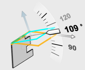
- Orientation plane: Specifies the angle with
the help of an existing selected plane or surface.
-
Under Limiting Geometry, do the following:
- Specify the offset values for the start and end points of the wall on the perpendicular
edge.
- Click
 to reverse the direction of offset creation. to reverse the direction of offset creation.
- Select the From reference check box to create the offsets with
respect to the reference.
- From the Position list, specify the width limits for the interior
or exterior of the wall on edge.
- Click Swap offsets to swap the offset values
with each other.
-
Under Bends, do the following:
-
Select With Bend check box to retain the
default bend settings.
By default, this check box is selected. Canceling the selection
creates wall without bends.
-
Select Override default settings check box
to specify new bend parameters.
- Specify the value for Bend radius.
- From Relief 1 and Relief 2, select one
of the following options:
| Option | Description |
|---|
| Minimum with no relief |
The bend corresponds to the common area of the supporting walls
along the bend axis, and shows no relief. |
| Square relief |
The bend corresponds to the common area of the supporting walls along the bend axis,
and a square relief is added to the bend extremity. The Length 1 and
Length 2 parameters can be modified. |
| Round relief |
The bend corresponds to the common area of the supporting walls
along the bend axis, and a round relief is added to the bend
extremity. The Length 1 and Length 2 parameters can be modified if
required. |
| Linear |
The unfolded bend is split by two planes going through the
corresponding limit points (obtained by projection of the bend axis
onto the edges of the supporting walls). |
| Tangent |
The edges of the bend are tangent to the edges of the supporting
walls. |
| Maximum |
The bend is calculated between the furthest opposite edges of
the supporting walls. |
| Closed |
The bend corresponds to the intersection between the bends of
the two supporting walls. The closed bend extremity lies on the
surface of the encountered bend. |
| Flat joint |
The two bends are joined in flat view. |
- Specify the value for K-factor.
Linked to SheetMetal parameters  shows that the given parameter is driven from the global sheetmetal
parameters. You can click to unlink it.
  shows that the given parameter is a local or custom value.
 Click
Linked to SheetMetal parameters  beside K factor to get the options, Bend
Allowance and Bend Deduction for
bend calculation. Specify the value for bend allowance or bend
deduction. beside K factor to get the options, Bend
Allowance and Bend Deduction for
bend calculation. Specify the value for bend allowance or bend
deduction.
-
Under Offset Wall, select one of the following
Offset Type options:
- No offset: Creates a wall with the existing
settings.
-
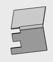
Wall with no offset
- Custom radius offset: Creates a wall at a
specific distance from the perpendicular edge in two
directions.
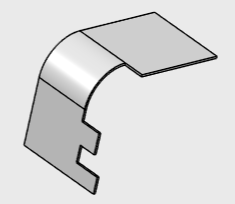
Note:
The offset wall and angle values are relative to the selected plane.
-
Click
 to
save and exit. to
save and exit.
Create a Wall from Edge from Sketch
You can create a wall by selecting an edge of an existing wall and a sketch.
Before you begin: Create a sketch perpendicular to an
existing wall as below. 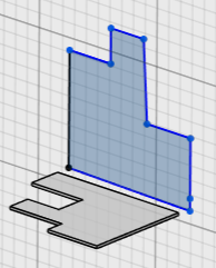
-
From the Sheet Metal section of the action bar, click Wall on
Edge
 . .
-
On the Wall on Edge dialog box, click
Sketch.
-
Click Edges, and from the work area, select an edge of an existing wall.
-
Click Sketch, and from the work area, select a sketch that is perpendicular to an existing wall.
-
Click
 to reverse the direction of the wall if the profile extends to both sides
of the selected edge. to reverse the direction of the wall if the profile extends to both sides
of the selected edge.
-
Click Material side to flip the material side of the
wall on edge.
-
Specify the value in the Angle field.
Alternatively, from the work area, you can use the angle handle to specify the angle value.
-
Under Bends, do the following:
-
Select With Bend check box to retain the
default bend settings.
By default, this check box is selected. Canceling the selection of
the check box removes the default bend parameters.
-
Select Override default settings check box
to specify new bend parameters.
- Specify the value for Bend radius.
- From Relief 1 and Relief 2 list, select
one of the following options:
| Option | Description |
|---|
| Minimum with no relief |
The bend corresponds to the common area of the supporting walls
along the bend axis, and shows no relief. |
| Square relief |
The bend corresponds to the common area of the supporting walls along the bend axis,
and a square relief is added to the bend extremity. The Length 1 and
Length 2 parameters can be modified. |
| Round relief |
The bend corresponds to the common area of the supporting walls
along the bend axis, and a round relief is added to the bend
extremity. The Length 1 and Length 2 parameters can be modified if
required. |
| Linear |
The unfolded bend is split by two planes going through the
corresponding limit points (obtained by projection of the bend axis
onto the edges of the supporting walls). |
| Tangent |
The edges of the bend are tangent to the edges of the supporting
walls. |
| Maximum |
The bend is calculated between the furthest opposite edges of
the supporting walls. |
| Closed |
The bend corresponds to the intersection between the bends of
the two supporting walls. The closed bend extremity lies on the
surface of the encountered bend. |
| Flat joint |
The two bends are joined in flat view. |
- Specify the value for K-factor.
Linked to SheetMetal parameters  shows that the given parameter is driven from global sheetmetal parameters.
You can click to unlink it.
  shows that the given parameter is a local or custom value.
-
Under Offset Wall, select one of the following
Offset Type options:
- No Offset: Creates a wall with the existing
settings.
- Distance offset: Creates a wall at a specific
distance from the perpendicular edge in one direction.
You can specify values for Distance,
Direction, and Support
type.
- Custom Radius Offset: Creates a wall a
specific distance from the perpendicular edge in two
directions.
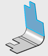 The highlighted portion in the above images is a new wall created
from sketch having Bend and Custom radius offset properties
applied. -
Click
 to
save and exit. to
save and exit.
Create Multiple Walls from Edges
You can create multiple walls at once by selecting multiple edges of an existing wall.
Before you begin: In the work area, create a wall.
-
From the Sheet Metal section of the action bar, click Wall on
Edge
 . .
-
In the Wall on Edge dialog box, click
Edges and from the work area, select more than one edge of an existing wall.
-
Specify properties such as Wall height,
Inclination, Limiting
Geometry, Bend, and
Clearance.
- Optional:
Specify the Gap Value to define the gap between the
intersecting walls at the corners of the edges.
The properties are common for all the walls.
|


 to reverse the direction of the wall on an edge.
 in the panel to expand the Wall on Edge dialog box.
 .
The wall is created on the edge.
 shows that the given parameter is driven from the global sheetmetal
parameters. You can click to unlink it.
  shows that the given parameter is a local or custom value.

