Create a Standard Cutout
Before you begin: Create a wall that has closed
sketch on it.
-
From the Sheet Metal section of the action bar, click Cutout
 . .
-
In the Cutout dialog box, click
Standard
and
from the work area, select a sketch as a profile.

-
For Limit type 1 and Limit type
2 lists, select one of the following:
| Option | Description |
|---|
| Dimension |
Creates the cutout using a depth value. |
| Up to next |
Creates the cutout up to the next surface. |
| Up to last |
Creates the cutout up to the last surface. |

When you drag the handle, you can see the preview. Shaded preview
appears on the release of the handle. The area in sheet metal where the
cut happens have preview in the yellow color. In the above image,
the Limit value is Up to Last. By default, the
Limit to thickness check box is
selected.
-
Under Cutout direction, select the following
options:
-
Click Direction to specify the cutout
direction.
-
Click Revert cut direction to invert the
direction of an extrusion.
-
Click Revert material side to invert the
direction of a material side.
-
Under Impact Options, from the Face
type list, select one of the following:
- Top to select the top face to begin with the
cutout.
- Bottom to select the bottom face to begin
with the cutout.
-
Click Faces to select specific face with selected
face type to that you want to cut out.
If you do not select any face, by default all the faces are selected for
cutout.
-
Click
 to
save and exit. to
save and exit.
 Note:
You can use equations for all numeric parameters. Click the
dimension text. The dimension text becomes editable. Type =
in the input field, to open the Equation dialog box and enter
a formula or number. For more information, see
Equations..
Create a Pocket Cutout
Before you begin: Create a wall that has closed sketch on it.
-
From the Sheet Metal section of the action bar, click Cutout
.
-
In the Cutout dialog box, click
Pocket
 and
from the work area, select a sketch as a profile. and
from the work area, select a sketch as a profile.
-
Specify the values for Limit 1 and Limit
2.
-
Under Cutout direction, click Revert
material side to invert the direction of a material
side.
-
Click to
save and exit.
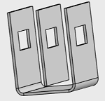
Pocket cut out with Dimension Limit type.

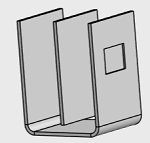
Pocket cut out with Dimension Limit type extended up to the top
face of the middle wall.
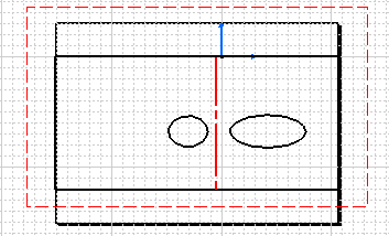
Create a Cutout of an Open Sketch
Before you begin: Create a wall that has an open sketch on it.
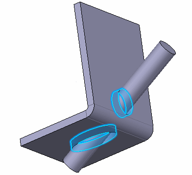
Create a Cutout of a Cylinder
You can create a cutout on both the bottom and the top face of a cylinder.
|