Creating a Bend | |||
| |||

-
From the Sheet Metal section of the action bar, click Bend
 .
.
-
Click Support 2 orientation to change the orientation of Support
2 for bend creation.
The following table illustrates the behavior of Support Orientation options. As an example, we are selecting the vertical wall as Support 1 and a horizontal wall as Support 2.
Option Description 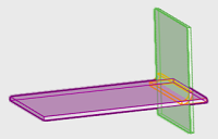

Support Orientation 1 and Support Orientation 2 enabled The orientation of the vertical wall is facing left and the horizontal wall is facing upward. This type of orientation supports the bend creation. 

Support Orientation 1 is disabled and Support Orientation 2 enabled The orientation of the vertical wall is facing right and the horizontal wall is facing upward. This type of orientation supports the bend creation. 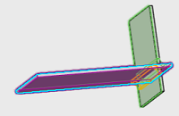
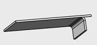
Support Orientation 1 is enabled and Support Orientation 2 disabled The orientation of the vertical wall is facing left and the horizontal wall is facing downward. This type of orientation supports the bend creation. 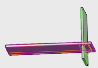

Support Orientation 1 and Support Orientation 2 disabled The orientation of the vertical wall is facing right and the horizontal wall is facing downward. This type of orientation supports the bend creation. -
Click Extremities to do as follows:
- Select Override default settings check box to specify new bend parameters.
- Specify the value for Bend radius.
- From the Relief list, select one of the following options:
Option Description Minimum with no relief The bend corresponds to the common area of the supporting walls along the bend axis, and shows no relief. Square relief The bend corresponds to the common area of the supporting walls along the bend axis, and a square relief is added to the bend extremity. You can modify the Length 1 and Length 2 parameters as per your requirement. Round relief The bend corresponds to the common area of the supporting walls along the bend axis, and a round relief is added to the bend extremity. You can modify the Length 1 and Length 2 parameters. Linear The unfolded bend is split by two planes going through the corresponding limit points (obtained by projection of the bend axis onto the edges of the supporting walls). Tangent The edges of the bend are tangent to the edges of the supporting walls. Maximum The bend is calculated between the furthest opposite edges of the supporting walls. Closed The bend corresponds to the intersection between the bends of the two supporting walls. The closed bend extremity lies on the surface of the encountered bend. Flat joint The two bends are joined in flat view. Linked to SheetMetal parameters
 shows that the
given parameter is driven from global sheetmetal parameters. You can click to unlink it.
shows that the
given parameter is driven from global sheetmetal parameters. You can click to unlink it.
 shows that the given
parameter is a local or custom value. You can click Relink All to
reset all values to global sheet xmetal parameters.
shows that the given
parameter is a local or custom value. You can click Relink All to
reset all values to global sheet xmetal parameters.
- Specify the value for K-factor.
Click Linked to SheetMetal parameters
beside K
factor to get the options, Bend Allowance and Bend
Deduction for bend calculation. Specify the value for bend allowance or
bend deduction. -
Click
 to save and
exit.
Note: You can use equations for all numeric parameters. Click the dimension text. The dimension text becomes editable. Type = in the input field, to open the Equation dialog box and enter a formula or number. For more information, see Equations.
to save and
exit.
Note: You can use equations for all numeric parameters. Click the dimension text. The dimension text becomes editable. Type = in the input field, to open the Equation dialog box and enter a formula or number. For more information, see Equations.