Workflow in the Single Modeling Environment | ||
| ||
Within a single workspace, called a product, you can create sketches, features, bodies, and components. No distinction is made between assembly files and part files.
Opening a New Product
When you open the app, a new product opens. The design tree displays the product name and the
default reference geometry (the Top, Front, and
Right planes and Origin). 
Creating Geometry
In the product, you can create sketches, add features, and create solid bodies. The sketches, features, and other geometry are listed in the design tree.
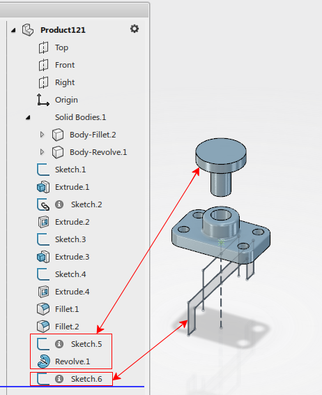
In this example, you extrude sketches, add cut extrudes, and add fillets to create
a base plate.
Then, in the same
product, you revolve a sketch to create a knob. You also add a sketch of a platform, but you do
not add any 3D features for it.
Moving to a Component
As your design evolves, you can make items into components. When you make an item into a component, you move its geometry into a separate new product. The item remains in the current product as a component, but it can also be opened separately. The item can also now be used as a component in other products.
Various
commands are available for converting items into components. In this example, you use the
Make Component command to move the base plate to a separate component.
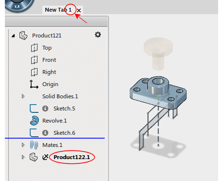
The base plate still appears in the work area of the original product.
The sketches and features of the base plate are still listed in the tree of the original product, but they are moved to a new product that is a component of the original product.
| Before Moving | After Moving |
|---|---|

|

|
- Create a new component product from sketch entities.
- Insert a new, empty product as a component of the current product.
- Insert an existing product as a component of the current product.
Editing Components
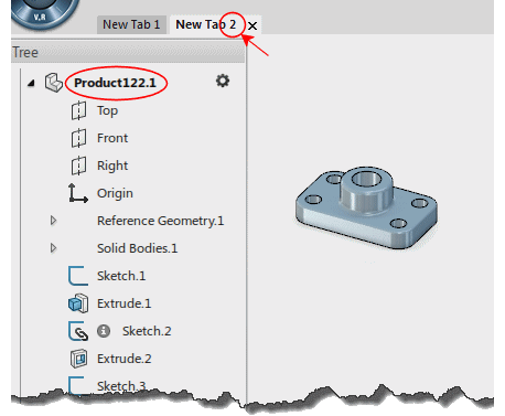
If you need to edit the base plate, you can activate it for editing within the assembly, or open it in its own separate tab.
| Within the Assembly: |
|---|

|
| On a Separate Tab: |
|---|

|
Design Methods
Within the single modeling environment, three main design methods are used when modeling assemblies: bottom-up, top-down, and master model. As you model an assembly, you can use one method, or mix techniques from each method.