Master Model Design | ||
| ||
The master model workflow is especially useful for designing stylized molded products with multiple components.
In this example of the master model workflow, you create solid bodies to represent the different pieces of the assembly. As you add features to create a solid body, you reference the features of other solid bodies as necessary to maintain design intent. You can also use Split features to split a solid body into multiple related solid bodies. After creating sufficient solid bodies to represent the design intent of the model, you use the Master Model command to convert the solid bodies to derived components.
In the master model workflow:
- Changes you make to the master model propagate to the derived components.
- Changes you make to a derived component apply only to that component.
| In a new tab, add features to create multiple solid bodies. |
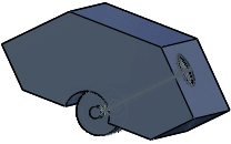
|
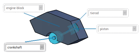
From the Assembly section of the action bar, click Master Model
 to convert the solid bodies to derived components. to convert the solid bodies to derived components. |
|
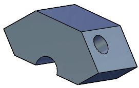
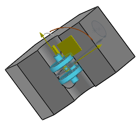
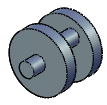
Master Model converts the solid bodies to derived components. You can open the derived components in their own tabs and modify them.
| Master Model | Derived Component | |
|---|---|---|
| engine-block |

|
|
| crankshaft |
|
|
| connecting rod |

|

|
| piston |

|

|
After creating the master model, the design tree updates to include the derived components.