Top-Down Design | ||
| ||
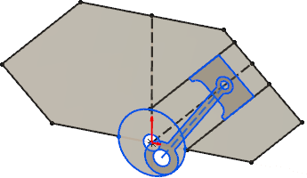
In this example, the layout sketch defines the overall layout of multiple components. Once the layout sketch is complete, you create solid bodies from the sketch profiles.
| Create a layout sketch of your mechanism. Optionally use Instant Motion to test the mechanism. |
 |
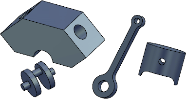
| Add components using the Insert New Component command from the Assembly section of the action bar. Extrude from the layout sketch or use the layout sketch as a guide to create new components. |
 |
| Add additional features, components, and mates as necessary. |
 |
Alternatively, you can follow a simplified workflow:
| Create a sketch mechanism by clicking Sketch Mechanism from the Sketch section of the action bar. Optionally use Instant Motion to test the mechanism. |

|
| Create 2D components by clicking Sketch to Components on the Assembly section of the action bar. |
 |
| Extrude from the 2D components or use the sketches as a guide to create 3D parts. You can also open components in their own tabs to add features. |
 |