Robot Handles
When the Robot is displayed, use the Robot handles to manipulate objects. By default, the Robot is displayed on the center of objects in the work area.
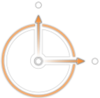
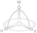
The components of the Robot are defined as follows: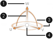
- (1) Axis label
- (2) Axis arrow
- (3) Arc
- (4) Center
The axes, arcs, and center are the Robot handles. When a Robot handle is selected, it turns blue and enables you to manipulate the position and orientation of the object. Drag the blue axis handles to move objects linearly along the selected axis or the arc handles to rotate objects about the selected axis.
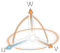 | Axis handle |
 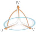 | Arc handles |
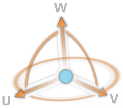 | Center handle |
 command. This is also the view when using the
 option the dialog box to flip the direction of the axis.
 beside the component in the design
  to view the component again.
 ).
).
 the
the 


