Align and Quick Align Points on the Subdivision Mesh

You can align subdivision cage points on objects using commands from the action bar or the context toolbar.

This task shows you how to:

Aligning Cage Points

You can align cage points on a subdivision object with other objects in the work area.

  1. From the Subdivision section of the action bar, create a 2D or 3D subdivision object.
  2. From the Subdivision section of the action bar, click Align Cage Points .

    Note: Press Esc to exit the command, double-click to apply the current command and use the command again.

  3. From the Align Cage Points dialog box, under Alignment Type, click one of the following alignment options:
    OptionDescription

    Align to Edges and Curves

    Aligns the vertices to sketch entity or curve.

    Align to Geometry

    Aligns the vertices to other geometry.

    Align to Body

    Aligns the vertices to another body.

    Align Sub-D Elements to each other

    Aligns edges and faces to subdivision entities.

    Align Vertices to each other

    Aligns the selected vertices using the first two entities.

  4. Depending on your alignment option, select the entities to align.
    OptionDescription

    Vertices

    Selects vertices, the alignment is with the first two vertices or to the entity.

    Curve

    Selects curve entity to align with vertices.

    Entities

    Selects entity to align with vertices.

    Geometry

    Selects edges or faces, the alignment is with the first selection.

    Body

    Selects body to align with vertices.

    Edges and Curves

    Selects the edges, sketch entities, or curves to align with the vertices.

    Alignment Entities

    Contains the subdivision entities used to constrain the alignment.

    Note: The selected entities should be connected for the alignment to work.

  5. Optional: When using the Align to Edges and Curves option, you can set the following alignment options:
    OptionDescription

    Edges and Curves

    Selects the edges, sketch entities, or curves to align with the vertices.

    Tangent Propagation

    Includes tangent continuous edges to the selection.

    Flip Profile Orientation

    Modifies the orientation of the profile.

    Note: Click Flip Profile Orientation to flip the orientation of the vertices along the selection.

  6. If you are in the subdivision environment, for quick access, you can also access the Alignment Type options from the command toolbar. Click to collapse the existing dialog box and switch to the command toolbar. The command toolbar appears with the following commands:
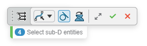
    CommandDescription
    Command Icon On a subdivision object, when you launch a command with a command toolbar, the active command icon is displayed on the drag handle of the toolbar. In the screen capture above this table, the Align Cage Points icon is shown.
    Alignment Type. Determines the type of alignment.

    Click to select from the list of alignment types available.

    Tangent Propagation. Includes tangent continuous edges to the selection.
    Flip Profile Orientation. Flips the orientation of the vertices along the selection.
    Selection Tab. Displays the current active selection field.
    Next Selection Field. Activates the next available selection field.
    Expand Dialog. Restores the full Align Cage Points dialog box.


    OK. Accepts the current result and closes the command.


    Cancel. Cancels the command.
  7. Optional: When Align Sub-D Elements to each other is clicked in the Align Cage Points dialog box, under Mode, click one of the following:
    OptionDescription

    Collinear or Coplanar

    Aligns all selected items to the first selected edge or face.

    Parallel

    Aligns parallel to the first selected edge or face.

    Orthogonal

    Aligns orthogonal to the first selected edge or face.

    Coincident

    Aligns all selected items to the same line or plane.

  8. Optional: Click in Align Cage Points dialog box.
  9. Drag the mesh points and faces to customize the shape of the box.

    To assist with selecting the mesh entities, the following options are available:

    • For faces, press i or o to select a face loop around the subdivision. Click near an edge of the face, to select the direction of the loop.
    • For edges, press i to select edge rings around the subdivision, or press o to select edge loop around the subdivision.

  10. Click .

Quick Align

When working with 2D or 3D subdivision objects, you can quick align multiple vertices using the context toolbar.

  1. Select two or more vertices in the mesh you want to align.
  2. From the context toolbar, click any one of the following:
    OptionDescription
    Align Entities by Line. Aligns the selected objects to a draggable line with handles.
    Quick Align. Aligns the selected objects with a sketched line.
  3. Optional: In the dialog box, click to turn the auto rotate view on.
  4. Click in the dialog box.
  5. Click .