About 3D Coordinate System | ||
| ||

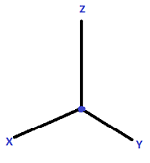
Consider the origin as the corner where two walls and the floor of your room meet. Imagine that you are facing the corner.
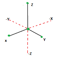
The X-axis is the horizontal line along which the vertical wall on your left and the floor intersect. The Y-axis is the horizontal line along which the vertical wall on your right and the floor intersect. The Z-axis is the vertical line along which the left and right walls intersect.

The XY plane is the horizontal plane spanned by the X and Y axes which in this case is the floor of the room. The XZ plane is the vertical plane spanned by the X and Z axes which in this case is the left wall of the room. Similarly, the YZ plane is the vertical plane spanned by the Y and Z axes; the right wall of the room.

The visible portion of the lines of the walls while you are standing in the room is the positive portion and the portion that goes outside of the room is the negative portion.

If you consider the Z-axis as the thumb on your right hand and you curl your fingers from the positive X to the positive Y direction, the result is a right handed coordinate system. If you curl the fingers of your left hand considering the thumb as your Z-axis, the result is a left-handed coordinate system. SOLIDWORKS follows the right-handed Cartesian Coordinate System as a default 3D Coordinate System.
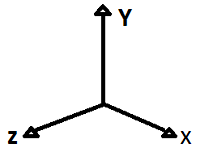
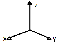
The orientation of your 3D model in the work area defines it as a Y-Up or Z-Up model.
 |
Y-up model orientation |  |
Y-up model orientation in SOLIDWORKS |
 |
Z-up model orientation |  |
Z-up model orientation in SOLIDWORKS xApps |