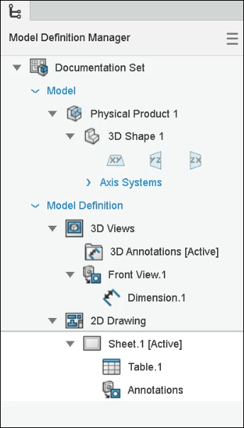
Model Definition Manager Panel | ||||
|
| |||
Panel Characteristics
- Document Set shows the annotation set.
- Panel displays physical product and reference planes. The physical product is under the Model node and all 3Dviews and 2D drawings comes under the Model Definition node.
- 3D views appear under 3D Views node. Annotations appear under each 3D view. New annotations are added to the respective view in the panel.
- If you create annotations before creating a 3D view, the annotations are added under 3D Annotations, which is always visible in the tree.
- You can create 3D View groups and organize 3D views in them.
- You can move annotations and folders to other 3D views or in the same view by dragging them.
- If you place a dimension in a wrong or different orientation, a warning
 appears
on the dimension icon in the panel.
 - The thumbnail of the 3D views, sheets, and the annotations appear in the order of creation.
- 2D sheets and 2D views appear under the 2D Drawing node in the tree.
- You can switch between 3D views and 2D drawings in the tree.
- The active context of the tree is displayed in white background.

Context Menu Commands for the Panel/Tree
| Command Icons | Command Name | Description |
|---|---|---|
 |
Activate 3D View | Activate the selected 3D view and it appears in the work area. You can work on it. |
 |
Manage 3D View | Edit the selected 3D view. |
| Delete | Delete the selected item. | |
 |
Show all annotations | Show all 3D view dimensions and annotations except flatten view. |
 |
Show only default view annotations | Show only dimensions and annotations placed in the default view. |
| Hide | Hide or show the annotations in the treeusing the Hide/Show command. Hidden annotations are grayed out. | |
 |
Add 2D View | Add 2D views in the sheet. For more information, see Adding MBD Views in Drawing Sheets. |
 |
View Scale | Specify the scale. |
 |
Text Font | Select text font type and size. |
 |
Edge Line | Select edge line font and thickness. |
 |
Annotation Line | Select annotation line font and thickness. |
For editing annotations from the panel, see Context Toolbar for Annotations.