Attaching an Action to an Existing Step | |
| |
-
Under More, select Associate direction to
step swiveling to apply modifications of the swiveling to the
tool direction.
Selecting the check box allow the edition of the step blank swiveling/part swiveling to impact the cam direction, not the press direction.
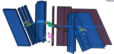
- Initial position without swiveling, with cams in yellow and other
cut tools using the press direction.
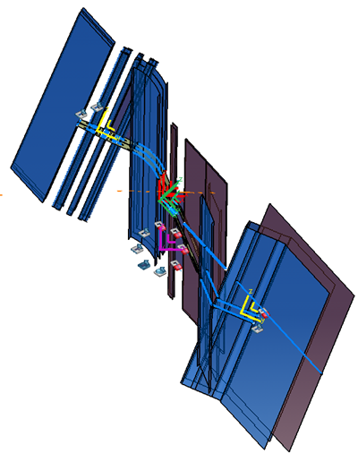
- After a blank swiveling, the cam axis has followed the swiveling and
the tool cutting surface direction, whereas the cutting tool in the
press direction has kept the same direction.
The check box is automatically selected if the tool direction is a cam direction
- Initial position without swiveling, with cams in yellow and other
cut tools using the press direction.