Defining a Process Step | |
| |
-
Define the Step Reference Position.
Process Step computes
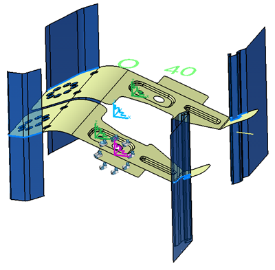
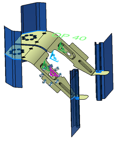
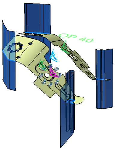
- The step axis system (purple), an initial blank axis system position (blue), and the
initial part axis system (green) from the reference position options.

- The final blank axis system (blue) and an axis system for each part from the
computed initial blank axis system position, using the blank swiveling.

- The final positioning of each part axis system (green) using the corresponding part
swiveling.

- Select Automatic
 for an automatic
positioning that uses the translation value defined in the corresponding method plan.
Additional rotation is possible.
 - Or Manual
 to use a
transformation (Translation and Rotation). Set required translation and rotation values
below.
 - Or Axis
 to use the
specified axis.
- The step axis system (purple), an initial blank axis system position (blue), and the
initial part axis system (green) from the reference position options.
-
Define the blank and part swiveling options, by editing the Robot.
The swiveling locally modifies the axis system of either the blank or the part, combined with the reference position. It allows adjusting the step geometries for an easier cut or waste removal, for example. When you open the dialog box for the first time, the Robot is on the blank axis system, thus allowing the swiveling of the blank.
- Open the Blank and Part Swiveling dialog box.
- Click Edit Swivel Robot Coordinates for a more precise positioning of the Robot.
- Click Reset Local Position to reset the swiveling.
-
Select the Part Separate check box to allow the swiveling of
each part.
Use this option when there is no cutting left between the parts, that is, when the parts are really distinct.
-
Select a part axis system to define a swiveling on the part, or the blank axis
system to define the swiveling on the blank.
The Robot is displayed on the selected axis system.
-
To create a symmetry between a driven part and a main part:
You can create as many symmetric parts as wanted, as well as a symmetric part from another.
- Activate Part Separate.
- Apply a swivel on the main part (Reference of the symmetry).
- Select the symmetric part or its axis system.
- Activate Select Symmetric Axis and select the main part axis system.
- Select the symmetry plane.
-
Define the detail design, that is the geometry of the output parts of the step.
This geometry includes the remaining scraps and compensation done in the detailed design and replaces the geometry computed from the process definition.
- Select the geometry for the detailed part.
-
Select the axis system for the detailed part.
When manually creating a method plan with already existing detailed geometries, it is sometimes useful to specify a different reference press axis system for each operation. For example, on some existing method plans, instead of rotating the geometry to execute a swiveling, the axis only is rotated. So the geometry is designed in a different reference axis.
After you have selected the axis system for the detailed part, the geometries of the corresponding OP are rotated to match the selected detailed part axis with the global press axis specified by the method plan.
- Under Geometries Parameters, verify and modify the types of holes.
| See Also |
| More help on this topic |