Creating a Stamp Partition | ||
| ||
-
Use the context toolbar to
- Specify the type of the surface
 Folded Surface
 Unfolded Surface
Special case of double-flanges
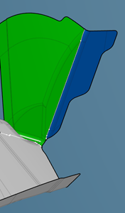
- A double-flange is a flange with its folding line in another flange. In this example, the fixed area of the blue flange is the green flange.
- To compute the unfolded view of the blue flange, the default direction is the mean normal of the flange faces connected to its folding line.
- To compute the unfolded view of the green flange,the unfolded view of the blue flange is joined to the green surface. The unfolded view of the green flange is computed from this join. The geometry of the blue flange is integrated in the green flange unfolded view.
- The unfolding sequence is integrated when planning the double-flange in the process.
 Stamped Surface
 Ignored.
 Prehem Surface.
- The selected flange is marked as ignored. It is removed from the list of elements to plan.
- Two unfolded view are computed, one at 90°, the other at 0°.
- The 90° view becomes the flange geometry at the end of the stamping process (prehemmed geometry)/
- The 0° view is its unfolded view at the beginning of the process.
 Reuse the geometry as
intermediate geometry.
Reuse the geometry as
intermediate geometry. Reframe on the selected element.
- Specify the type of the surface
- Alternatively, if the input is a stamping direction, click Create Unfold
 on the context toolbar.The unfolded surface is computed and automatically associated to the selected folded surface.