-
From the
Analysis & Preparation section of the
action bar,
click
Circle Analysis
 .
.
Note:
Quick Circle Analysis is available from the
Quick View section of the action bar.
-
Select a stamping direction.
-
Select the surface to analyze, or its boundary (3D Curve).
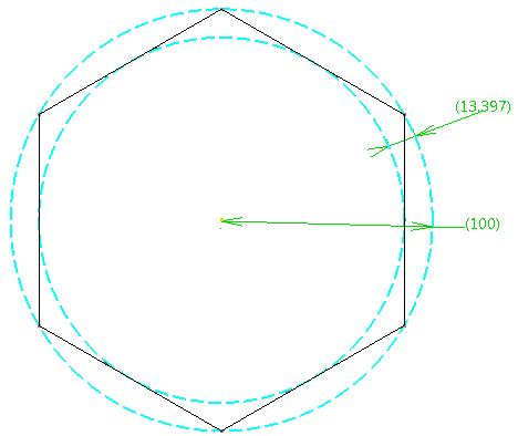
- A hole is circular if contained between two planar, concentric
circles (One inscribed, one circumscribed).
- Circular holes are identified in green, noncircular holes in red.
- The
Detected Maximum Circle Radius is
displayed in the dialog box (100 in the example below).
.
- Optional:
Edit the Minimum Tolerance For Circle Recognition and
Maximum Tolerance For Circle Recognition.
It corresponds to the distance between the inscribed and circumscribed
circles, 13.397 in the example below.

-
Pick a point on a hole.
The distance to the estimated circle center is displayed
in the
3D area.
-
Activate more options.
- Compute Areas
- Fly Analysis
- Hide 3D Labels
- Reframe on selection
-
Select a Color Mode
- Detailed
- Face/Edge
- Smooth.
-
Set the Mesh Behavior.
-
Enter the Interval Step.
-
Enter the Lay Down Tolerance.
The Maximum Lay Down
Deviation is displayed.
-
Go to Extract Geometry to convert the results of the
displayed analysis to dead geometry.
- Extract Areas: Stores the results as dead geometries and 3D
labels.
- Extract Direction: Extracts the Z-Axis on each
analyzed point.
- Extract Geometries as
Points.
- Extract Values as
Tags or Points.
- Extract Points Number using
Full, Minima and Maxima or
User Selection.
A
Circle Analysis feature is created.
Double-click the
Color Ramp inside the feature to edit the
colors.