Creating a Concept to Detail Link | ||
| ||
A link feature is created in the detailed part.
- Its name is Link to: <Reference Feature Name>
- It is created under a geometrical set, with the same name as the reference feature.
- It creates a data model that depends on the reference feature, as explained below.
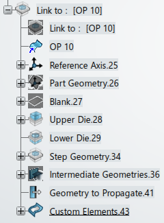
If linked to a process step
- Reference Axis set
- Reference Press Axis
- Reference Blank Axis: Blank axis without swiveling
- Reference Part Axis: All the part axes without swiveling
- Step Press Axis: Reference press axis translated to the OP position
- Step Blank Axis: Blank axis translated to the process step position, with swiveling
- Step Part Axis: Part axis, translated to the process step position, with swiveling
- Proxy Step Blank Axis: Step Blank axis translated from the step press axis to the reference press axis
- Proxy Step Part Axis: List of step part axes translated from the step press axis to the reference press axis
- Part Geometry
- Copy of the input part (result of the process)
- Copy of all additional elements, if the input part is a process positioning feature.
- Blank
- Copy of each blank section
- Upper Die
- A concept to detail link for each Tool of the OP in the Upper Die.
- Lower Die
- A concept to detail link for each Tool of the OP in the Lower Die
- Previous Step Detailed Geometry
- If detailed geometry was specified in the previous process step, it is copied in the current process step, with the right position and swiveling. Part swiveling is not applied.
- Step Geometry
- A Concept Geometry set: Concept result geometry out of the process step
- A Design Geometry set: Specifies the intermediate features used to design the step resulting detailed geometry.
- A Detailed Geometry set: Specifies the step resulting detailed geometry.
- Intermediate Geometries: List of flanges/intermediate geometries from the future OP, allowing the computation of the realistic trim line, for example , organized in sub sets Intermediate Geometries, Flange Areas, Stamped Areas.
- A concept to detail link for each custom geometry of the step.
- Geometry to Propagate set: Specifies the features propagated by the detail to detail link.

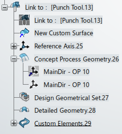
If linked to a process tool
- A Concept Process Geometry set
- Copy of the tool direction
- Copy of the input geometries
- A Design Geometrical Set: Specifies the intermediate features used to design the tool resulting detailed geometry.
- A Detailed Geometry set: Specifies the tool resulting detailed geometry.
- A concept to detail link for each custom geometry of the tool.

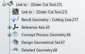
If linked to custom geometry
- A Concept Process Geometry set: Copy of the custom concept geometry.
- A Design Geometrical Set: Specifies the intermediate features used to design the custom geometry detailed geometry.
- A Detailed Geometry set: Specifies the resulting detailed geometry.
