Creating a Stamp Partition | |||
| |||
-
From the Method Planning section of the action bar, click Stamp Partition
 .
. -
Select:
- A surface. Creates a Stamped Surface geometrical result for each domain.
- A stamping direction. Computes a Folded Surface geometrical result for each area (faces) associated to a tool direction. For the other areas, creates a Stamped Surface geometrical result for each domain.
A Stamping Partition feature is created under Partition Set. - Select elements to cut the surface.
- 3D curves to directly cut the surface.
- Sketches. An internal extrude of the sketch in the plane direction cuts the surface at the intersection.
- Two points on the surface boundary. From the context toolbar, chain the edges.
Stamp Partition- Cuts the surface.
- For each domain of the input element, the type of the largest area is Stamped Surface, the type of other areas is Folded Surfaces.
- Under More, select one element to highlight it and verify it.
-
Use the context toolbar to
- Specify the type of the surface
 Folded Surface
 Unfolded Surface
Special case of double-flanges

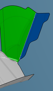
- A double-flange is a flange with its folding line in another flange. In this example, the fixed area of the blue flange is the green flange.
- To compute the unfolded view of the blue flange, the default direction is the mean normal of the flange faces connected to its folding line.
- To compute the unfolded view of the green flange,the unfolded view of the blue flange is joined to the green surface. The unfolded view of the green flange is computed from this join. The geometry of the blue flange is integrated in the green flange unfolded view.
- The unfolding sequence is integrated when planning the double-flange in the process.
 Stamped Surface
 Ignored.
 Prehem Surface.
- The selected flange is marked as ignored. It is removed from the list of elements to plan.
- Two unfolded view are computed, one at 90°, the other at 0°.
- The 90° view becomes the flange geometry at the end of the stamping process (prehemmed geometry)/
- The 0° view is its unfolded view at the beginning of the process.
 Reuse the geometry as
intermediate geometry.
 Reframe on the selected element.
- Specify the type of the surface
- Associate unfolded surfaces to folded surfaces.
You can select any surface as the unfolded result of a folded surface. This way, you can use results from other softwares.
- Select a folded surface.
- Select the unfolded surface to associate.
- Alternatively, if the input is a stamping direction, click Create Unfold
 on the context toolbar.The unfolded surface is computed and automatically associated to the selected folded surface.
 - Choose intermediate geometries to associate to the selected element.The table of results is updated.
- Click Manage Intermediate Geometries.
- Reorder intermediate geometries.
- Select intermediate geometries to cut.
A Partition Set is created.
Result areas are stored under geometrical sets:
- Planned Elements (Associated to a process action)
- Not Planned Elements (Not associated to any process action)
- Ignored Elements (Not used by the process).
- Stamped Surface
- Folded Surface
- Unfolded Surface
- Intermediate - name.