-
From the Method Planning section of the action bar,
click Unfold as Surface
 .
.
-
Select an axis system (stamping direction) as the reference axis.
-
Select the surface to unfold.
-
Select a fixed area (surface or wireframe element).
- Optional:
Select a support surface on which the unfolded surface is projected.
-
Select the type of output result.
- Unfold as Surface unfolds the selected surface as a planar
surface, possibly on a support.
- Unfold as Trim Line unfolds the selected surface as a trim
line, possibly on a support.
- Partial Unfold keeps the initial geometry and computes a
new fillet.
-
Specify the material definition.
-
Enter the thickness of the material.
-
Select a thickness orientation to create the surface.
- Top Surface: The material is below the surface with
respect to the unfolding direction. It is the choice by default.
- Middle Surface: The surface is in the middle of the
material.
- Bottom Surface: The material is above the surface with
respect to the unfolding direction.
-
Enter the KFactor, ratio of the neutral axis to the material
thickness.
-
Or select the Automatic KFactor check box to compute it
automatically.
-
Under Realistic Trim Line Computation, verify that it is
available and select the check box to activate it.
- Realistic Trim Line Computation requires that a core material
is applied to the surface to unfold.
- Realistic Trim Line Computation does not support
Middle Surface, nor Unfold as
Spec.
- Optional:
Under Advanced, invert the direction of the result.
-
Still under Advanced, select a Folding
Line type.
- Folding Line: The folding line is the intersection between
the fixed area and the surface to unfold. It is the default choice.
- Mean Line: The folding line is a line computed between the
first and the last points of the folding line.
- Mean Line From Axis: The folding line is the computed mean
line projected on the reference XY plane.
- Folding Line From Axis: The folding line is the
intersection between the fixed area and the surface to unfold, projected on the
reference XY plane.
-
Select faces on the surface to unfold with geometry to ignore.
This is useful for bulldozers, for example.
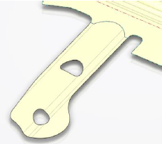
- Example of unfold with no faces to ignore
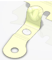
unfolds as
- whereas when a face to ignore is selected (in orange)
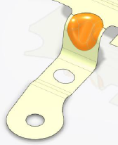
unfolds as
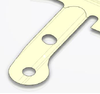
The selected faces are considered as plugged holes when
computing the unfold.
-
Under Partial Unfold/Automatic Support Surface Computation
Options, select the type of fillet.
When computing a support surface (that is, when none is provided) or for the partial
unfold, a support surface with fillets is automatically created. Use these options to
customize the fillet algorithm.
- Automatic Fillet computes the fillet radius automatically
from the bend angle with the fixed surface
- With the specified maximum chord where the angle between the tangent of the
surface to unfold and the Z-Direction is minimum
- With the minimum chord where the angle is maximum.
- The radius for the other angles is computed by a linear interpolation.
- Manual Fillet defines the fillet using local radiuses on
the folding line.
-
For Manual Fillet (which lets you precisely manage the fillet
generation), a list of default local radii computed from the current automatic options is
proposed.
-
Select a radius in the list or in 3D area and
modify its value in the dialog box.
In partial unfold mode, the radius is not always respected (priority is given to
the geometry of the surface to unfold). However, the computed spline used to compute
the fillet is as close as possible to the specified value.
-
Alternatively, pick a vertex, select Add Target Radius
 from the context toolbar and enter its value.
-
Drag a local radius to move it.
-
Remove selected local radii.
-
Select a Leader Fillet Profile.
The leader fillet profile is used to compute the rotation of the
surface. It is the only fillet profile kept as is. Other target fillet profiles are
replaced by splines, that reach the rotated surface.
If you do not select a leader
fillet profile, the target fillet radius closest to the mean radius is used.
Depending on your choice, an Unfolded Trim
Line, Unfolded Surface or Unfold as
Spec feature is created under Unfold Set. Each feature
contains the parameters used for its computation.