Start Mesh Preparation
You can specify global parameters for the preparation of meshes, retrieve
information, and have a view on the quality of the mesh.
-
From the Prepare section of the action bar,
click Terrain Preparation
 and select the mesh.
-
Press
 to perform and retrieve
the results of the control. to perform and retrieve
the results of the control.
This panel is displayed as you enter Terrain Preparation.
-
Press Configure. Select the Mesh
Pathologies to check and validate.
- Global Check and Repair all request
apply to the selected pathologies.
- The Mesh Pathologies list is reset when you exit
Mesh Preparation.
-
Click Check.
-
Repair or delete pathologies as explained below.
-
Press
 and specify the global
parameters for the detection of problems and improvement of the mesh. and specify the global
parameters for the detection of problems and improvement of the mesh.
-
Expand the Detection section to specify the
Confusing distance used to repair confused vertices or the
Cleft distance to repair button holes.
-
Expand the Improvement section to determine the
Small angle threshold used to correct small angles, and the
Long edge threshold used to correct too long edges.
-
Press
 to retrieve information on
the mesh. to retrieve information on
the mesh.
The data cannot be edited, unless specified otherwise.
-
Expand each section.
-
Under Statistics and Display, specify the color of cells,
or highlight elements.
-
Under Graphic Properties, specify the display as
required.
Repair, and Improve
Pathologies are listed in sections, with possible actions.
Notes:
- After a pathology is repaired or deleted, a check is performed on only this pathology,
turning the global status in the top bar to "not up-to-date".
- Whenever possible, the color of the elements is preserved, with the following exceptions.
- Button holes and self-intersections: The mesh is reset to the default color.
- Newly created triangles and vertices are created with the default color of the
mesh.
-
Place the pointer over the callout.
An illustration of the defect appears on the left, except for All
defects.
-
On the right of a type, press
 to show all locations. to show all locations.-
 to navigate along the defects of that type using the arrows in the player.
-
 to repair all defects of a given type. to repair all defects of a given type.
-
 to delete all
defects of a given type. to delete all
defects of a given type.
-
Press on the right of
All defects to repair all defects listed under Mesh
Pathologies in one shot.
The repair action runs sequentially on each selected defect type, in a default
order.
-
Clear a defect type to skip it.
-
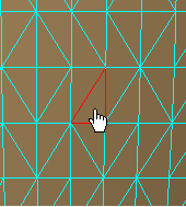
Press on the right of Mesh
Self-intersections.
- Self-intersection spots are highlighted in soft color. Their intersection line or
point is displayed in red.
- All self-intersection spots are automatically selected.
- Self-intersection spots are spots where triangles intersect each other, leading to
a self-intersection of the mesh.
- Self-intersection spots are identified within a cell, not on several.
- You cannot navigate from one self-intersection spot to another.
-
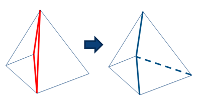
Press to repair all local
intersections. Local intersections are the most common geometric configurations
where there are slight overlaps between neighboring triangles and/or slivers.
Edges of two neighboring triangles are flipped, degenerated triangles that may
appear are then collapsed. Notes:
- The repaired mesh may deviate slightly from the initial one, the deviation
remaining very low with regard to the size of the model. If you have any doubt,
refine the repaired mesh and verify the deviation with the initial one.
- Repairing is more time consuming than deleting, but is a good alternative to
deleting and then filling the resulting holes.
-
For Holes and boundaries,
-
Select a boundary in the 3D area.
A toolbar is displayed under the pointer.
-
Use this toolbar to select or deselect the boundary, or zoom on the boundary to
perform a filling action.
-
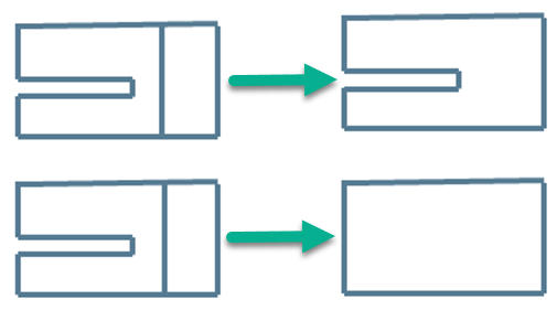
For Button Holes:
-
Modify the Cleft distance either globally in the
Parameters or locally under Button
Holes.
-
Click Show
Button holes are highlighted in red. All button holes are automatically
selected.
-
Click to repair all
defects.
All button holes are repaired. The existing vertex is inserted in the
facing edge to create a common edge instead of two free edges.
Notes:
- Button holes are identified within a cell, not on several.
- You cannot navigate from one button hole to another.
- No selective repair.
Remesh
You can either regenerate a defective mesh or create an external envelop around it.
Check the Mesh Structure
You can correct structure issues in the mesh.
Check Holes and Boundaries
You can manage holes and boundaries.
Edit the Mesh
You can edit the mesh to repair it.
Note:
Available edition tools depend on the installation, you might have not access to all
edition tools.
-
In expand the section of the App.
-
Under Display Modes, under Mesh
clear Free edges and select or clear
Triangles as required.
-
Press Create Triangle
 and do one of the following.
- Enter three points (vertices of an existing mesh or not).
- Two neighboring edges of a mesh (with a vertex in common).
- An edge of an existing mesh and a point (vertex of an existing mesh or
not).
- The pointer provides a visual help.
- To select an edge or a vertex, move the pointer from inside to outside the
mesh.
- When several items are found around the pointer, only one is highlighted, priority
being given to vertices, then to edges. Zoom in to select the required item.
-
Press Add point
 and pick the point to add, existing or not.
-
Press Move point
 . .
Available for a single point, not for a set of points.
- Either pick the 3D area to
define the new position of the point.
If you pick a triangle or an edge and drag
without releasing the pointer, the closest vertex is moved to the pick and follows
the pointer motion. If you pick a triangle or an edge without dragging, the
closest vertex is moved to the pick location. You can adjust the
coordinates.
- Or pick a vertex and enter the xyz coordinates of the new position
(Absolute is selected).
- Or pick a vertex, clear the Absolute check box, and
enter a signed distance to move the point on each global axis.
-
Press Remove element
 . .
-
Select the type of element to remove (on the right).
-
Pick the element to remove.
-
Press Collapse element
 . .
-
Select the type of element to collapse (on the right).
-
Pick the element to collapse.
-
Press Flip edge
 and pick the edge to flip.
You cannot flip free edges.
Optimize Triangles
|

 Mesh
pathologies information is not up-to-date.Note: To improve productivity, this status lets you work on the mesh. Information resulting from a specific action is updated, whenever possible. However, if you try to show a pathology that no longer exists, the action is canceled, and the pathology line disappears.
Mesh
pathologies information is not up-to-date.Note: To improve productivity, this status lets you work on the mesh. Information resulting from a specific action is updated, whenever possible. However, if you try to show a pathology that no longer exists, the action is canceled, and the pathology line disappears. Up-to-date
information, no pathologies.
Up-to-date
information, no pathologies. Up-to-date
information, pathologies found.
Up-to-date
information, pathologies found. and enter required
parameters.
and enter required
parameters.
 .
.
 to split connected zones in different cells.
 or
or  to edit
orientations.
to edit
orientations. to smooth all the boundaries.
  to fill holes.
 to edit the
mesh.
to edit the
mesh. to switch to ghost
mode.
to switch to ghost
mode. to display
triangles.
to display
triangles.