Available Formats
The list of formats available for import varies with the apps available in your session.
If you have access to Digitized Shape Preparation, all the formats are available, not only in Digitized Shape Preparation, but also in Digitized Shape Sculpting, 3D Printing Preparation and 3D Printing (if you have access to those apps). - Via
- ASCII RGB
- ASCII User Format
- ASCII Free
- Atos
- Cgo
- Gom-3d
- Hyscan
- Iges
- Kreon
- Opton
- Steinbichler
- Stl
- Via Drag and Drop
- ASCII RGB
- ASCII User Format
- ASCII Free
- Atos
- Cgo
- Gom-3d
- Hyscan
- Iges
- Kreon
- Opton
- Steinbichler
- Stl
- Digitized Shape Preparation with access to Virtual to Real Shape Morphing
- ASCII Vector Field via the dialog box or via drag and drop.
- Digitized Shape Sculpting with no access to Digitized Shape Preparation
- 3D Printing Preparation with no access to Digitized Shape Preparation
- 3D Printing with no access to Digitized Shape Preparation
Common Options
Some options apply to all formats.
- Grouped
- Select the
Grouped
check box to group the files in one output feature.
- Clear the
Grouped
check box to create one feature for each imported file.
- Sampling (%)
- Determines
the percentage of points or scans or grids that are read from the digit file.
Note:
The
Sampling percentage is not relevant to formats related to
mesh entities (for example STL format).
- Scale factor
- Determines the scale factor to be applied to the data imported.
- File unit
- Determines in which unit the data are imported.
Specific Options
When relevant, the dialog box displays options that are specific to the selected format. Some of these options are not available when you import files by drag and drop.
- ASCII Free
- Direction. Not available with drag and drop.
- Delimiters
apply to scans.
Enter these
data whenever you know them.- ASCII User Format
Imports additional information attached to the points, such as point
symbol or color. They are taken into account as point
properties. Depending on their type, some imported point information can be
taken into account in the cloud of points display:
- Color attribute: Select the Colored check box in the Display Modes tab of the properties of the import result
to use the information from the digit file. Otherwise, the current
display is applied.
- Display symbol: Select the Symbol check box in the
Display Modes tab of the properties of the import result
to use the information from the digit file. Otherwise, the current
display is applied.
- Information text (displayed under the cursor): Select the Dynamic display of
information check box in to display information from the
digit file.
Notes:
- To enable this import, you must describe the user format in a
.FDF file (Format Description File) and enter the path of this file
in the dialog box.
- If the format description file is not found, invalid
or if the input file does not correspond to the format described,
import operation fails and a specific error message is
displayed.
- All user information is imported but not all of them have an influence.
- If the format contains more than once text attribute, all texts
are displayed under the mouse cursor (one text per line).
- The input file cannot contain redundant or conflicting information (2 different color attributes
for example).
- If the input file contains a specific property not described in
the format file, this property is ignored at best or an error
message is displayed and import fails.
- There is no user mapping table management. For example, a point
symbol attribute can only have one of standard symbols
value.
- If the point description does not have a specific property, the
point is displayed with the standard default representation.
- ASCII User Format Description File
- This file is a simple one line ASCII text file.
The format is described by a set of keywords separated by a space.
Each keyword indicates the type of expected data.
Notes:
- Keywords can be defined in any order. However, the digit file
must respect the order in which you have defined the keywords.
- The format must be described on a single line in the file.
- Only the X, Y and Z information is required in the format. Other keywords are optional.
- RGB color and color index information cannot be used
simultaneously in the format.
- You can define more than one TEXT information in the
format.
Additional information attached to the points, such as point
symbol or color, are imported and taken into account as point
properties. Available keywords are defined in the following table: | Keyword | Type | Definition | Value | Mapping | Comment | | X | double | X coordinate of the point | | | | | Y | double | Y coordinate of the point | | | | | Z | double | Z coordinate of the point | | | | | DX | double | | | | | | DY | double | | | | | | DZ | double | | | | | | R | integer | Red component of point color | [0..255] | | Must be associated with G and B | | G | integer | Green component of point color | [0..255] | | Must be associated with R and B | | B | integer | Blue component of point color | [0..255] | | Must be associated with R and G | | A | integer | Alpha component of point color | [0..255] | | | | COLOR | integer | Color index in the color table | 0 | BLACK | | | | | 1 | WHITE | | | | | 2 | RED | | | | | 3 | GREEN | Default value | | | | 4 | BLUE | | | | | 5 | YELLOW | | | | | 6 | MAGENTA | | | | | 7 | CYAN | | | SYMBOL | integer | Marker used for point display | 0 | SMALL_DOT | Default value | | | | 1 | DOT | | | | | 2 | STAR | | | | | 3 | FILLED_SQUARE | | | | | 4 | FILLED_CIRCLE | | | | | 5 | CONCENTRIC | | | | | 6 | CIRCLE | | | | | 7 | PLUS | | | | | 8 | CROSS | | | LABEL | string | Such a text is only for file readability. It is not imported. | | | The text does not contain space character | | TEXT | string | Free text | | | The text must be enclosed in double-quotes | | USELESS_INFO | | Useless information. It is not imported. | | | | Example:- In the Format Description File:
LABEL X LABEL Y LABEL Z SYMBOL TEXT R G B TEXT - In the imported file:
X -11.855023 Y 21.734158 Z -101.254105 2 "43°30'28.46N,5°29'27.84E" 255 128 34 "PT215"
X -10.756025 Y 23.764214 Z -100.732541 0 "43°30'26.40N,5°30'26.40N" 255 128 34 "PT225"
- ASCII Vector Field File
- This format allows the import of displacement vector fields, to be used in Digitized Shape Preparation, before switching to Virtual to Real Shape Morphing.
- This ASCII file contains only the description of vectors:
- Origin and direction as X, Y, Z DY, DY, DZ
- One line per vector.
- The file extension is asc_vec.
- The unit applied to the coordinates and direction is the one defined in the import dialog box.
- Similarly, the scale factor applies to the coordinates and direction.
- Sampling, Scale factor and Statistics are available. No other specific options.
- Import by the dialog box results in a feature, import by drag and drop results in a datum (Not
associative with the initial file).
- By default, a vector is represented by its origin (point) and vector (segment). Regarding Properties,
Notes:
- The cell color has priority over the cloud color defined in the Graphics tab.
- If the points are colored, they have priority over the cell color.
- Atos
- Minimal Point Quality: Cleans
the file from invalid points.
The quality value of a point lies between 0 and 255 (low to
high).
Choose a value to ignore points below that value.
- Gom-3d
- Files are imported as points, scans, grids or meshes.
- Minimal Point Quality: Cleans
the file from invalid points.
The quality value of a point lies between 0 and 255 (low to
high).
Choose a value to ignore points below that value.
- Create facets: Creates or not the
facets (triangles) of the imported mesh
- IGES
Direction: Applies to scans. Select the required option
whenever you know it. IGES Entities 116 are processed.
If the cloud to import is made of Entities 116 only, the result is
a cloud of points.
Otherwise, the result is made of scans. - Steinbichler
- Files are imported as points, grids or scans.
- STL
Both bin or ASCII STL formats are supported.
- Create facets: Creates or not the
facets (triangles) of the imported mesh.
- Outwards orientation: The mesh orientation is not taken from the STL but
specified to outwards.
- LIDAR
- When you select Lidar, Classification and Return Type options are available in the Options tab. You can filter all standard LIDAR points classes and return types by clicking filter
 . In the Classification and Return Type dialog boxes that appear, select the check boxes of interest. . In the Classification and Return Type dialog boxes that appear, select the check boxes of interest. At least one check box must be selected. The imported LIDAR files reflect the filtered selection you made. The resulting cloud is created with several cells, each cell
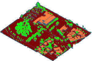
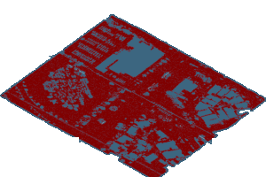
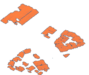
corresponding to a classification. Both a color and a name are associated to the cells you can modify. Consider the following import examples with: -
All check boxes selected.

- Only Ground check box selected (classification)

- Only Building check box selected

Notes:
- Only .las and .laz extensions can be managed.
- If colors are defined on points, they are imported.
- Lidar points marked as "withheld" are not imported.
- Lidar points outside of the bounding box defined in the header
of the file are not imported.
- If possible the CRS is retrieved in the
file and proposed as Source CRS.
For more information about Lidar export options, see Terrain Preparation User's Guide: About Lidar Format.
|


