About Planar Sections | ||||
|
| |||
Except for the input curves and elements, the parameters of the dialog box are modal.
Choose a view parallel to the screen.
Multi-selection is available.
Input elements can be:
- Clouds of points
- Meshes
- Surfaces
- Volumes.
If input elements are surfaces or volumes, they are automatically tessellated within the command with a Sag value that you can edit.
Output elements can be:
- Scans, distinct or grouped
- Or curves.
- No output mesh is produced.
- Grouped output can be grouped in one entity, or by element or by plane.
Cutting planes can be defined by a reference plane, or a guide line, or by independent planes.
User selection filter can be used to select limiting curves, but not to select the guide curve.
Creating planar sections on a mesh rather than on a cloud of points has some advantages:
- The preview is dynamic on meshes.
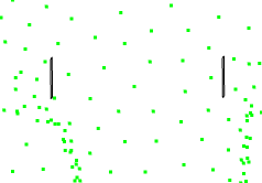
- In the case of a cloud of points, the intersection may be
interpolated, since the plane does not necessarily
intersect points.

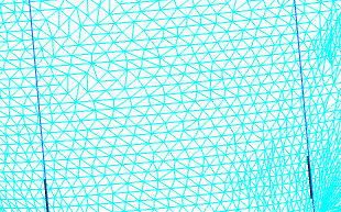
- That problem is reduced with meshes since the plane intersects
facets,
providing a better accuracy.

If you process a hybrid CloudsUnion element made of a mesh and a cloud of points, the planar sections are created on the mesh only.
Possible outputs for planar sections are listed below.
If Grouped is not selected:
| Output in Planar Sections | Output in XYZ Automatic Planar Sections |
|---|---|
Scans are created as distinct Planar Sections.
 | Scans are created as distinct Planar Sections (one entity for each section and for each element to cut in the 3 directions). |
If Grouped, In one entity are selected:
| Output in Planar Sections | Output in XYZ Automatic Planar Sections |
|---|---|
Scans are created as one group of Planar Sections | Scans are created as one group of Planar Sections in each direction. |
If Grouped, By plane are selected:
| Output in Planar Sections | Output in XYZ Automatic Planar Sections |
|---|---|
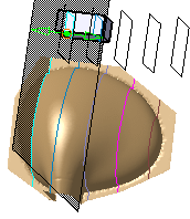
Scans are created as one group of Planar Sections
for each cutting plane.
 Note:
The Planar Sections are created in a
different color for each plane.
 | Scans are created as one group of Planar Sections
for each cutting plane. Note:
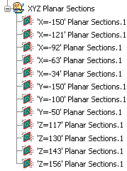
the name of each planar section contains the abscissa of the cutting plane along the direction.
|
If Grouped, By element are selected:
| Output in Planar Sections | Output in XYZ Automatic Planar Sections |
|---|---|
Scans are created as one group of Planar Sections for each element selected. The name of the Planar Sections contains the name of the related element.  | Scans are created as one group of Planar Sections for each element selected. The name of the Planar Sections contains the name of the related element.  |