Detecting Defects in a Terrain | |||
| |||
-
From the
Tools section of the
action bar,
click
Draft Analysis
 .
.
- Set up your analysis:
- In the Mode area, select Full Analysis Mode.
- In the Display area, select Show/Hide color scale
 .The Draft Analysis.x dialog box is displayed. It shows the color scale and identifies the corresponding values for the analysis. if you need to use other options:
Option Description Quick Analysis Mode 
Displays a simplified analysis based on only three values and four colors, displayed by default.
Full Analysis Mode 
Displays a complete analysis based on the values and color scale you define. This allows you to study the distance performed on the selected element.
Show/Hide color scale Turns the color scale on or off. By default, the color scale shows two angle values and three colors. For more information, see About the Draft Analysis Color Scale.
On the Fly 
Displays the draft analysis results at the current position of the cursor.
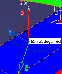
The on the fly analysis provides:
- The direction of the draft marked D and is identified by a red arrow. It is similar to the robot's Z axis
- The normal to the surface is marked N and identified by a green axis
- The tangent to the surface is marked T and identified by a blue arrow
- The plane tangent to the surface are identified by circles
- The angle between the draft direction and the tangent to the surface is expressed by a value (reverse highlighted)
No Highlight Representations 
Turns off highlighting for the selected terrain mesh.
Light effect 
Applies a light effect on the selected terrain mesh.
Highlight Invalid area Provides color buttons to highlight specific areas of the terrain according to a color scale associated with angle values. You can click one or several buttons at a time.
By default, the three available color buttons are reflected in the Quick Analysis Mode color scale along with two values ranging from -90 deg to 2 deg:
- Blue: -90 deg to 0 deg
- Red: 0 deg to 2 deg
- Green: 2 deg to 90 deg
Both colors and values can be modified from the color scale window. To suit your analysis type, you can save a new color scale using the Color Scale Variant. This variant is stored in a CATPrefences file and can be reused for a further draft analysis.
Lock 
Locks the draft direction even when the robot is used.
Robot 
Drops the robot onto the model. It allows you to define a new draft direction by moving it.
Reverse 
Reverses the draft direction for each element involved in the current analysis.
Note: In most cases, use this option before launching the analysis. -
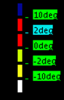
Edit the color scale and the values to detect defects. For example, create a color scale ranging from -10 deg to 10 deg where:
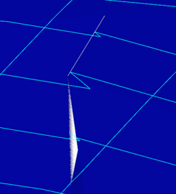
Note: The overhangs, embankments are identified when at least two "points" of the terrain are on the same normal to the surface.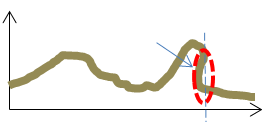
-
Click
the color buttons in the Highlight Invalid Area.
- Cliffs are identified in red

- Overhangs in yellow

- Triangle folding in white.
- Cliffs are identified in red