In 3D Simulation, designate a robot or a physical organizational resource as the ASO.
From the Analysis & Output section of the action bar, click Analyze Targets.
The Spot Analysis Scenario dialog box appears.
If a physical organizational resource is the ASO, all of the robots in the
physical organizational resource are considered for analysis and listed in
the Robot list. Depending on the current selected
robot, the corresponding weld analysis data (trajectories, tool profiles,
configs and welds) is displayed.
Multiple robot analysis is not supported for fixed TCP robots. If the
physical organizational resource has fixed TCP robots and mobile TCP
robots, only the mobile TCP robots are considered for the analysis. Each
fixed TCP robot must be analyzed separately.
If the Point Fastening operations implemented by
the robot do not have spot weld trajectories, a new spot weld trajectory
is automatically created for each point fastening operation and all of
the manufacturing welds are added to Welds in the
Analyse Target Orientation dialog box.
If the robot implements a General operation and
the Point Fastening operations owned by the
General operation do not have spot weld
trajectories, a new spot weld trajectory is automatically created for
each Point Fastening operation.
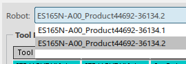
Select a robot from the Robot list.
The dialog box is updated with the weld details corresponding to the selected
trajectory. The entries in Tool Profiles,
Robot Configs, and Fasteners/Spot
Targets frames are specific to the selected robot in the list.
Note:
Point Fastening operations, General operations, spot weld trajectories or
compound spot trajectories can be selected at any time while
Analyze Targets is active. Selecting any of
these entities adds the corresponding manufacturing welds to the
Spot Analysis Scenario dialog box.
If a General operation is selected, manufacturing welds of the spot weld trajectories
aggregated under child Point Fastening operations are added to the
Fasteners/Spot Targets list. Spot weld
trajectories are created for any child Point Fastening operations that
do not contain a spot weld trajectory.
If a Point Fastening operation is selected that
already contains a spot weld trajectory, the manufacturing welds of the
spot weld trajectory are selected and added to the
Welds list. If the Point
Fastening operation does not contain a spot weld
trajectory, a new spot weld trajectory is created.
Select a weld gun.
Note:
If you want to use any of the weld guns defined as can-use resources on
the process or the weld guns associated with the trajectory in the weld
analysis, you must create tool profiles on the robot for each weld gun
before using Analyze Targets.
Note:
Fixed TCP Tool Profiles are listed with a ToolType
of Stationary.
Note:
Multiple tool profiles can be selected by pressing the
Ctrl key on the keyboard as selections are
made.
Double-click a row in the Tool Profiles list to select
one or more home positions for a particular weld gun.
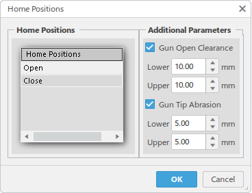
The Home Positions dialog box appears.
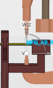
From the Home Positions section, you can check the
robot and gun accessibility for the specified fasteners with the
Open and Close home
positions. Select one or both of the available home positions in the list.
You can select multiple positions by holding the Ctrl
key as you make the selections.
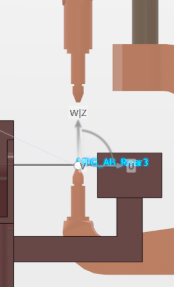
Open position Close position
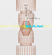
From the Additional Parameters section, you can also
specify values to consider Gun Open Clearance (Open
with TCP offset) and Gun Tip Abrasion (Close with
worn tooltip condition, gun joint offset plus TCP offset).
Open with TCP offset Close with worn tooltip and TCP offset
Select a configuration for the selected robot from the Configs list
under Robot Configs.
Note:
Multiple configs can be selected by holding the
Ctrl key as selections are made.
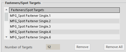
Select and edit welds as needed in the Fasteners/Welds list.
Welds can be removed from the list by selecting them and clicking
Remove. All welds can be removed with
Remove All. Note that welds removed from the list
are not removed from the data.
In the Parameters frame, select Compute from Start angle
and End angle to force the computation from the specified
Start Angle to End Angle even
if a feasible solution is found. When not selected, the computation for a
fastener/weld stops as soon as a feasible solution is found.
Select Check for collision to check for any collisions
in addition to the reachability check. When not selected, only a reachability
check is performed.
Select Compute with Tool flipped to check the
reachability status at each fastener location with the tool flipped.
Set the Collision Tolerance value.
Set the Computation step angle to define the angle step
at which the weld gun should be rotated for computation.
Collision objects indicates the number of objects that
are checked for collision. To edit/view the collision list, select
Edit the list of collision objects.
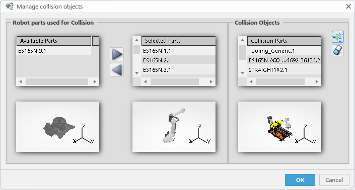
The Manage Collision Objects dialog box appears.
In the Robot parts used for collision frame:
By default, the Selected Parts list contains
all the parts of the robot except its base, and Available
Objects list contains only the robot base.
Objects in each of the lists are displayed in the respective viewer
below each list.
You can move any object between Available
Parts and Selected Parts
lists using the arrow buttons and , or by double clicking the object to move in the viewer.
Selected objects are cross-highlighted between entries in the list,
the viewer below the list, and in the work area.
In the Collision objects frame:
By default, Include all Objects is enabled. This means the Collision Parts
list includes all of the objects except for those objects in the
Robot parts used for Collision list.
You can remove any part from the list if that part should not be
considered for collision analysis by selecting the object followed
by Remove object.
You can empty the Collision objects list by
deselecting Include all objects.
Click OK to accept any changes made and close the
Manage Collision Objects dialog box.
Collision objects in the Spot Analysis
Scenario dialog is updated with the proper number of
objects.
For Servo weld guns, you can expand Weld Gun Additional
Parameters to reveal options for Gun Open
Clearance and Gun Tip Abrasion.
These parameters are as described in Step 5, above.
Default values for Weld Gun Additional Parameters can
be defined in Me > Preferences > Simulation > Process Engineering > Tool Analysis
After all of the analysis parameters are set, click OK
in the Spot Scenario Analysis dialog box.
The settings are stored in the current scenario.
If no welds are selected for a given robot, that robot is not considered for analysis and
a notification is displayed.
If no tool profile is selected for a robot, a notification is
displayed.
 .
.


 .
.
 and
and  , or by double clicking the object to move in the viewer.
 is enabled. This means the Collision Parts
list includes all of the objects except for those objects in the
Robot parts used for Collision list.
is enabled. This means the Collision Parts
list includes all of the objects except for those objects in the
Robot parts used for Collision list. .
.