This procedure describes how to generate 2D sections of selected fasteners. You
can view the sections with or without a weld gun.
The 2D section for a fastener represents the section of the contour of the products and
resources when the section plane is passing through the z-x plane of the fastener.
Before you begin: You must be in
3D Simulation.
From the Analysis Commands section of the action bar, click Generate
Sections.
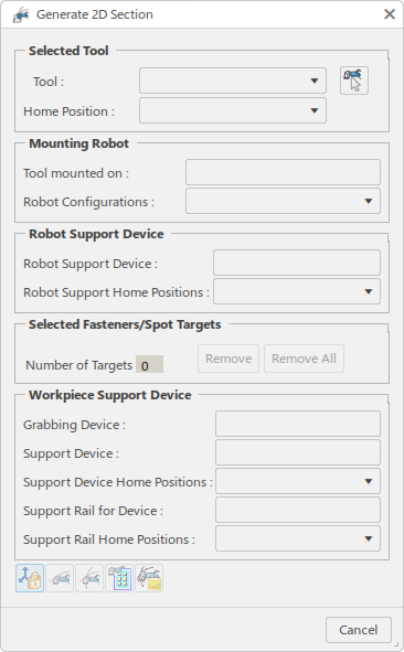
The Generate 2D Section dialog box appears.
In the Selected Tool section, click Pick
Tool to
select a tool in the work area if a Tool is not already selected.
The dialog box is populated with the selected tool, its defined home positions, and
the robot that it is mounted on.
Choose the fasteners to be analyzed by selecting any of the following:
Existing spot welds.
A compound spot trajectory.
A general operation.
The Selected Fasteners/Spot Targets list is populated as you
make selections.
If you select a General operation, the child
Point Fastening operations aggregate the spot
weld trajectories. The manufacturing welds of the spot trajectories are
added to the Selected Welds list. In addition,
spot weld trajectories are created for any child Point
Fastening operations that do not aggregate a spot weld
trajectory.
If a Point Fastening operation is selected that
already contains a spot trajectory, the manufacturing welds of the spot
weld trajectory are selected and added to the Selected
Welds list. If the Point
Fastening operation does not aggregate a spot
trajectory, a new Spot weld trajectory is created.
If fasteners are selected, use Pick Device to
select the weld gun. In this scenario, the name of the spot weld
trajectory remains empty, while the selected fasteners and weld gun are
displayed in the dialog box. If the weld gun is mounted to a robot, the
robot information is also displayed.
When a spot weld trajectory is selected that has a weldgun assigned, its
name is displayed in the dialog box. If the weld gun is mounted on a
robot, the robot is also displayed.
Note:
You can remove welds by selecting them in the list and clicking
Remove. Using Remove to
remove a weld from the list does not remove the weld from the spot weld
trajectory.
Click Section Settings to
define section generation options.
The Section Options dialog box appears.
Clash Detection activates collision during section
generation.
Volume Cut displays the cross section of objects cut
by the section plane in the 3D viewer.
Hide Section Plane hides the section plane for the
active weld.
Width and Height specify the
size of the section window.
Select a spot weld fastener or manufacturing weld.
The weld gun snaps to the weld and a context toolbar providing the Flip Tool and
Commit Position
commands appears.
As the weld gun is manipulated around the manufacturing weld, the robot jogs accordingly when
the manufacturing weld point is reachable for the robot-gun combination. If
the manufacturing weld point goes out of reach of the robot, the robot stops
jogging and only the gun rotates around the z-axis of the manufacturing
weld. This occurs until the gun reaches a position where the manufacturing
weld point is again reachable for the robot.
When Clash Detection is enabled in Section
Options, collisions detected are those between the selected
weld gun (and mounting robot, if the gun is mounted) and the remaining
objects in the world (all products and resources). If no collision is
detected between these objects, collision between the weld gun and the
mounting robot (excluding the robot mount plate) is also verified.
Use Flip Tool to flip the
selected weld gun at the current fastener.
The section corresponding to the current fastener is immediately updated in
the section window.
When Flip Tool is used with a fixed TCP weld gun, the
robot is jogged so that the part with the current weld is flipped.
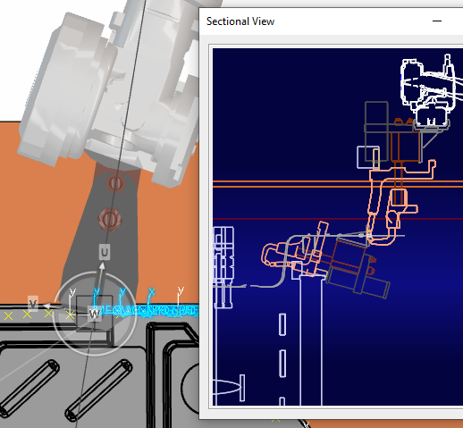
In he Generate 2D Section dialog box, click Generate
Section to
generate section curves.
The Sectional View panel appears.
As the weld gun is rotated, the section curves are automatically updated in
the Sectional View panel.
In the Generate 2D Section dialog box:
Lock Location
locks the translation of the manufacturing weld that is selected.
Show Only Active Section displays the section curves for only the active manufacturing
weld. By default, section curves are shown for all manufacturing
welds in the Selected Fasteners/Spot Targets
list. Show Only Active Section enabled
Click Commit Position to save
the position of the modified manufacturing weld.
Note:
If the selected fastener is implemented by an associated point fasten
process and the corresponding fasten process does not have a point
fastening operation to create spot weld trajectory, a message is
displayed: The data does not have any Point Fastening operation to
create spot weld trajectory, do you want to create it?
Click Yes to create a System structure that
contains a point fastening operation for the new spot weld trajectory.
Modifications applied to each selected weld result are saved in the
corresponding manufacturing weld in the spot weld trajectory. Also, the
context toolbar is updated to include all other commands that are associated with the
spot weld trajectory (Reassign Welds and
Reset to Design Position).
If you select No, the System structure and spot
trajectory are not created, and Commit Position
terminates without saving the modifications.
Note:
If the selected Fastener is not implemented by an associated Point
Fasten Process, a message is displayed and the weld position is not
saved: The following fasteners are not assigned to any
process. So, manufacturing welds are not created for these
fasteners.
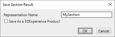
Click Save Section to save the
section curves.
The Save Section Result dialog box prompts you to name
the saved section.
Enter a
Representation Name and click
OK.
The section curves are saved in an Analysis Result object for the active scenario in the
Resultsside tab.
You can right-click the result object and select View Section Results
to view a list of section results that have been saved for the current
scenario.
You can select any result in the list and click Open to view the saved
section curves.
Click
OK to create a Weld Section scenario.
The new scenario appears in the Scenariosside tab.
Note:
If you select Cancel to terminate the command, any new sections
added under the results object are deleted.
 .
.
 to
select a tool in the work area if a Tool is not already selected.
The dialog box is populated with the selected tool, its defined home positions, and the robot that it is mounted on.
to
select a tool in the work area if a Tool is not already selected.
The dialog box is populated with the selected tool, its defined home positions, and the robot that it is mounted on.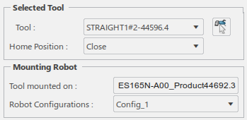

 to
define section generation options.
to
define section generation options.

 and
Commit Position
and
Commit Position
 commands appears.
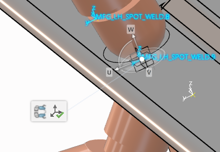
 to
generate section curves.
to
generate section curves.
 locks the translation of the manufacturing weld that is selected.
  displays the section curves for only the active manufacturing
weld. By default, section curves are shown for all manufacturing
welds in the Selected Fasteners/Spot Targets
list.
displays the section curves for only the active manufacturing
weld. By default, section curves are shown for all manufacturing
welds in the Selected Fasteners/Spot Targets
list. 
 to save the
section curves.
to save the
section curves.
 side tab.
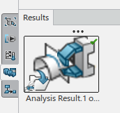


 side tab.