Selecting Multiple Tools for Feasibility Analysis | |||||
|
| ||||
-
From the
Analysis Commands section of the
action bar,
click
Tool Search
 .
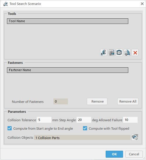
The Tool Search Scenario dialog box appears.
-
In the Tools section, click Catalog
Browser
 to
query for the guns from a catalog in the database.
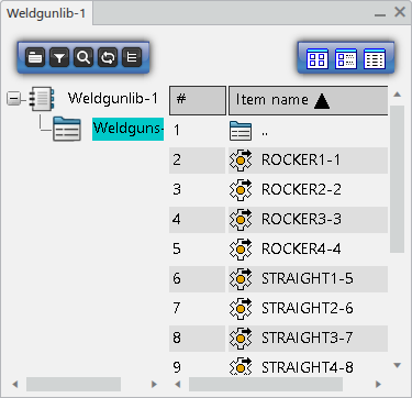
The first time you use the Catalog Browser, you are prompted to perform an applicative search for a catalog to open. From the top bar, enter a search term to locate the Weldgunlib catalog.
 The Weldgunlib catalog dialog box lists the available weld guns to choose from.
-
Select weld guns from the list in the catalog.
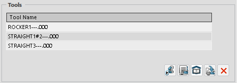
The Tools list is populated with the weld guns as you select them.
- Optional:
The following other methods can also be used to select weld guns to add to the
Tools list.

Click Pick Device to select a weld gun in the work area. 
Click Library Browser to perform an Applicative Search to find weld guns stored in a library. 
Click Search Tool to perform an Applicative Search to find weld guns in the database. 
Click Remove Tool to remove a selected tool from the list. -
Select any of the following to populate the list of
Fasteners to be analyzed.
-
Spot weld trajectory or Compound Spot trajectory
All manufacturing welds in the selected trajectory are added to the Fasteners list.
-
General operation
Manufacturing welds of the spot weld trajectories aggregated by child Point Fastening operations are added to the Fasteners list. Spot trajectories are created for any child Point Fastening operations that do not aggregate a spot weld trajectory.
If any aggregated punctual operation implements non-spot weld fasteners, no trajectory is created. Instead, all fasteners implemented by the punctual operation are added to the Fasteners list.
-
Point Fastening operation
If a Point Fastening operation is selected that already contains a spot trajectory, the manufacturing welds of the spot weld trajectory are selected and added to the Fasteners list. If the Point Fastening operation does not aggregate a Spot trajectory, a new Spot weld trajectory is created.
-
Spot weld design fastener
The selected spot weld design fastener is added to the Fasteners list. Design fasteners are distinguished from manufacturing welds in the list by an asterisk (*).
-
Fastening process
The Design fastener implemented by the selected Fastening process is added to the Fasteners list.
The Fasteners list is populated with welds for analysis.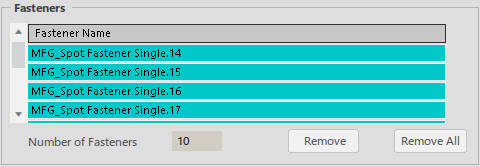
You can select fasteners and click Remove to remove them from the list. Remove All removes all fasteners from the list.
-
-
Set the Parameters to further refine the analysis.

Collision Tolerance specifies the tolerance value in mm between colliding objects.
Step Angle specifies the step size of the different angles that are analyzed. A larger step size results in a more rapid analysis, while a smaller step size provides a more detailed analysis.
Allowed Failure determines the extent to which the analysis is conducted on all of the welds in the activity. If you define an Allowed Failure rate of 0, the analysis ceases for the current tool when an inaccessible weld is discovered. If you define an Allowed Failure rate of 100, all welds are analyzed for a given tool.
Collision Objects indicates the number of parts that are selected to be considered for clash analysis. Click Edit the list of collision objects
 to view or modify the list of objects to consider.
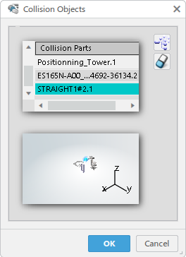
In the Collision Object dialog box, Collison Parts lists the parts selected for clash analysis.
Click Add all objects to the collision list
 to consider all objects in the work area. You can click it a second time to remove everything from the list, and
instead select specific objects in the work area to add to the list. Click Remove Selected object from the
collision list
 to remove
specifc objects.
 -
Click OK to close the Tool Search
Scenario dialog box.
All entered data is stored in the current scenario, and you are ready to simulate the scenario and generate results that you can analyze.
-
From the Analysis Commands section of the action bar, click Simulate and Generate Results
 to simulate
the scenario.
The Simulate and Generate Results dialog box appears.
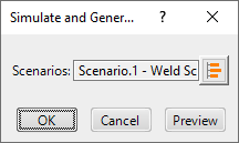
By default, the current scenario is selected for simulation.
-
Click OK to begin the simulation.
Once the simulation is complete, new results corresponding to the specification are created under the Results side tab.

- To view and edit the weld results, see Analyzing Tool Search Results.