Selecting Geometric Elements
This task describes how to select geometric elements on V4 Models.
- Open a model in 3DEXPERIENCE.
-
Above the geometry area where the V4 model is displayed, click the workspace tab you wish to display (the FUSELAGE
workspace in the model shown below, for example), the tab selected then "rises" relative to the other tabs.

-
If you then wish to select a geometric element, expand the specification tree by clicking on the FUSELAGE item and then on one
of the items with a plus sign, *SET5, for example. The specification tree will then look like this:

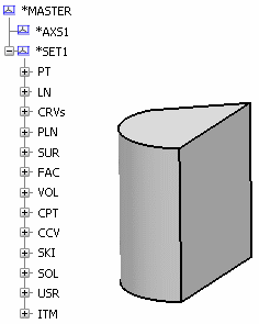
A set is made up of subsets each containing lines, curves, surfaces, solids, dittos, etc. In the specification tree shown above these are easily identifiable (LN, CRV, SUR, etc.). A subset can be selected just like any other item for copy/paste, show/no-show operations, etc. However, you can of course select one or more of the lines, curves, solids, etc. contained in the subsets.
-
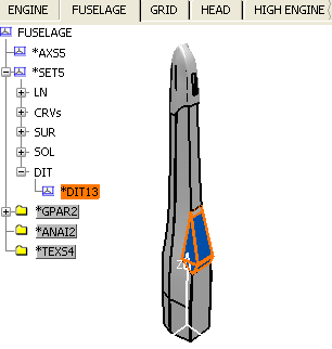
Click the plus sign of the DIT subset and select the contents, *DIT13.
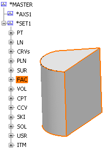
Notice that the corresponding part of the model in the geometry area is highlighted as shown below:
You can select an element by clicking it in:
the Specification Tree
the geometry area
by traps, for more information see, 3D Modeling Apps | 3DEXPERIENCE Platform | Working on Objects | Selecting | Selecting Using the Selection Traps.
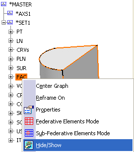
Note that if you select a Ditto (DIT) in the Specification Tree, you select all the components within the Ditto. For instance, if you hide a Ditto by transferring it to the No Show space, all the objects under Ditto will no longer be displayed in the Geometry area.
-
Click the central part of the fuselage (not the
blue component shown above). The corresponding solid is highlighted in the specification tree:
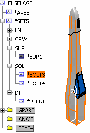
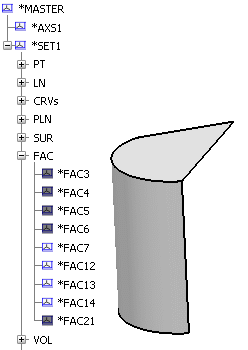
As you can see above, in the specification tree, double-clicking boxes with a plus sign shows the component elements of that particular workspace or set. Clicking the minus sign hides the elements contained in the workspace or set.
