- From the Review section of the action bar, click Cumulative Snap
 . .
The Cumulative Snap dialog box appears.
The icons are dimmed. If the two selected
geometric elements are two lines, two planes, an axis system
and a line or an axis system and a plane, the icons
will be activated. You can reverse the snapping direction
by clicking the appropriate icon.
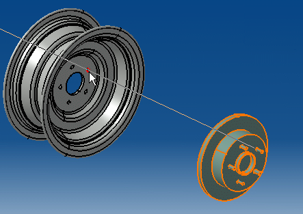
- Select the component to be moved, for example the disk cylinder.
- Select a geometric element (a point, line, plane or
axis system) on the same to-be-moved component, e.g. a circle of which
the center is the center of the entire disk cylinder.
- Select a geometric element on the component to which
the to-be-moved component will be snapped, e.g. a circle of which the
center is the center of the entire rim cylinder in the sample product
henceforth referred to as the receiving component).
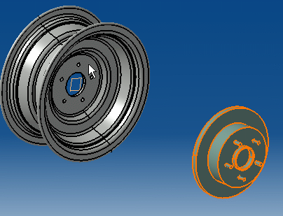
The first constraint is created. The disk cylinder is displaced in accordance
with the first constraint. You can continue directly to the creation
of the second constraint.
- Select a geometric element on the to-be-moved component,
e.g. the axe passing through one of the nuts of the disk cylinder.
- Select a geometric element on the receiving component,
e.g. the axe passing through one of the nut holes of the rim cylinder.
The second constraint is created. The disk cylinder is displaced
in accordance with the second constraint. You can continue directly
to the creation of the third constraint.  - Select a geometric element on the to-be-moved component,
for example the plane of the disk cylinder containing the nuts.
- Select a geometric element on the receiving component,
for example the plane of the rim cylinder containing the nut holes.
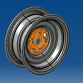
The third constraint is created. The two components have
been placed together as a function of the three constraints.   - Rotate to verify that the snap has been implemented
as desired.
|