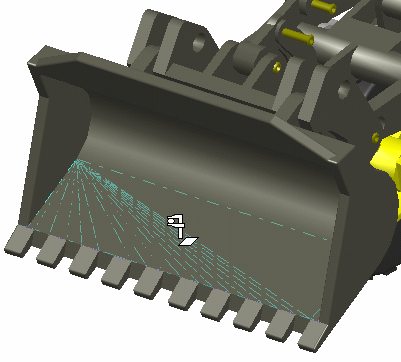
- From the Review section of the action bar, click Measure Item
 . .
Several things now happen:
-
The arrow pointer
 changes
to the measure pointer changes
to the measure pointer
 . Depending on the position of the measure pointer, it will
also show a symbol indicating the object you can select
with it. For a list of all the measure pointers, see
Pointer Transformation. . Depending on the position of the measure pointer, it will
also show a symbol indicating the object you can select
with it. For a list of all the measure pointers, see
Pointer Transformation.
-
The Measure Item dialog box appears
with the Specifications tab activated and Customize tab unavailable.
-
In the Specifications tab:
-
Select a calculation mode.
-
Select a geometric element to measure in the 3D area or the tree.
To help you with your selection, the mask on the measure pointer

changes according to the geometry type when you hover over a geometry.
You can refine your selection by selecting the required geometry type in
the Selection mode box. Some or all of the
following selection modes may be available:
- Any geometry
- Picking point
- Point only
- Edge only
- Surface only
- Product only
- Edge limits
- Arc center
- Angle by 3 points
- Move the measure pointer
 over the geometry.
The symbol to the bottom right of the
pointer changes to reflect the geometry type and to help you with your
selection. Also, dynamic highlighting of geometric
entities helps you locate the item to be selected.

- Optional: Select the Keep Only Last Measure check box to display the last measure in the work area.
Notes:
- This check box is only available for multiple measures and when the
measure is non-persistent.
- By default this check box is clear.
- Click when the pointer is above the object whose geometric
properties you want to measure.
Several things now happen:
-
The selected object is highlighted in the geometry
and in the tree.
-
An information box appears, providing information about the properties of the selected geometry. Drag this box to
move it. A full list of detectable objects
is provided in Pointer Transformation.
-
A Measure item is created in the tree
under the Notes branch with the name Measurexxxx.y where
xxxx is the selected geometry type and y the number of measures
made under the same slide and for the same type of geometry.
- Using the same method as just described, select several
geometric entities.
After the second selection, the contents of the
Selection field change to show only the number of selected entities. - To see a detailed list of your selections, click the
 button to the right of the Selection box.
The Measure Selections dialog box appears.
- To remove any selections in the list, select the unwanted
line(s) and click Remove. You can also do this by reclicking
the selected entity in the geometry.
Note that you cannot remove all selections.
At each selection (or selection removal), the related
information changes interactively in the More Results>> section.
This information also appears in the information box.
The corresponding measures are added under the Notes item in the tree.
- Click OK.
- To edit an existing measure, you have three options:
-
Double-click the measure in the tree.
-
Double-click the information box in the geometry
-
Right-click the measure in the tree
and select [measure_name]
object>Definition... .
Once created in the tree, the selections
of non-associative measures cannot be modified. If you click the
 button, a warning message appears:
If you click Yes, all the selections will be removed from
the list in the Measure Selections dialog box. You can now
make new selections.
If you click No, the selection list remains unchanged.
Note that you can reopen any Measure to access the Customize
tab and the Results section.
- Optional: Measure the area of a planar surface.
- From the Review section of the action bar, click Measure Item
 . .The Measure Item dialog box appears. - Select a planar surface.
The 2nd Moment area is added in the dialog box with the following boxes: - IoxG: displays the moment of area of the surface about ox axis
- IoyG: displays the moment of area of the surface about oy axis
- IxyG: displays the product of moment of area of the surface about ox and oy axes
- Click OK.
The result is visible in the work area and the measure values are displayed in the measure text box.
|