Creating a User Swept Weld

You can create a user swept weld and generate the user weld symbol on a drawing.Using User Swept Weld, you can generate a swept weld and generate the use user weld symbol on a drawing.


Before you begin:
  • Use a closed profile with two output features inside the part body of the bundle of welds representation.
  • The 3D shape for the weld must be created in the weld representation.
  1. Select a weld body in the tree.
  2. Select the faces you need as supports.


    Tip: Ctrl + Click and contextual commands from the Supports list let you control the faces you need.
  3. Select the closed profile.
  4. Optional: To generate weld annotations on a drawing, specify a welding symbol, a weld size, and a weld length in Drafting Parameters.
  5. Optional: To specify a dashed weld, click the Type tab and select a creation mode.
  6. Optional: Select Generate Weld Impacts.
    The app performs a Boolean subtract of the weld shape from the plates being welded.
  7. Click OK.
    The user swept weld is created. It appears with aggregated supports and external references in the tree.
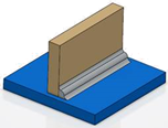
    • An assembly protected weld preparation is created and appears under the Assembly features node.
    • The welded 3D shapes are prepared.
      Important: In the tree, the weld impact appears as a feature in the PartBody including impacted 3D shapes. A rep impact is created, maintaining a link between the root product under which the bundle of weld, weld body, and welds are created. Rep impact appears under Impacts manager .