FTA Principal and Complementary Definitions
You can describe complete information with several characteristics for
requirement generation by specifying the principal and complementary annotations. This
helps manufacturing process in controlling the requirement generation in more specific
way. You can associate or dissociate the complementary annotations with its principal
annotation.
When you generate the manufacturing requirements, they are generated only for
principal annotations and not for complementary annotations. The data of each
complementary annotation is added in the attributes of its principal annotation. You
can differentiate between principal and complementary annotations as below:
- Principal annotation
- Any FTA dimension or annotation (semantic or non-semantic)
associated with a user surface can be a principal annotation.
- A principal annotation can have one or more complementary
annotations.
- A principal annotation can not be a complementary annotation of any
other principal annotation.
- When you select a principal annotation, all its complementary
annotations are highlighted.
- When a principal annotation is deleted, its complementary
annotations are not affected. Only the principal-complementary
association between them is removed.
- Complementary annotation
- A dimension or a semantic annotation cannot be a complementary
annotation.
- A complementary annotation has the same user surface as its
principal annotation.
- A complementary annotation can be complementary to only one
principal annotation and, in a tree, it is displayed as a child under the node of its principal
annotation.
- A complementary annotation cannot have another complementary
annotation associated with it.
- A complementary annotation may or may not have a positional link
with the principal annotation.
- If a complementary annotation is selected, its principal annotation
is also highlighted.
Definition of Text Properties
You can apply text properties to text, dimension text, text with leader,
balloon and datum target, as well as to text included in datum features and
geometrical tolerances. You can also set the properties of an annotation text (such
as font style, size and justification) either before or after creating the
annotation.
To set text properties, select the text and, in the Object
Properties panel, under Text Properties, choose the properties you
want to apply.
DS ISO 1 Open Type Font
When selecting a font style in the Text Properties, one of
the available choices will be DS ISO 1.
DS ISO 1 is an Open Type font based on the ISO 3098 standard defining the text representation. It is delivered along with the app
to ease the exchange of standardized documents.
The DS ISO 1 font supports new engineering symbols. You can access these engineering
symbols from the Engineering Symbols node in the
Standard Definition dialog box.
From a general standpoint, DS ISO 1 is a variable-pitch font, designed as Open Type
with True Type format outlines definition. It is designed based on ISO 3098-5:1997,
ISO 3098-3:2000 and Unicode definition (i.e. character codes are assigned in
accordance with Unicode definition). In particular, characters' shape, box and
dimensions are based on ISO 3098-5:1997, ISO 3098-3:2000 with lettering type CB
vertical (regular) and slopped (italic).
The bold style is not defined in ISO3098. A thickness is defined for the Bold and
Bold Italic styles, consisting in a 50% addition to that of the regular style.
DS ISO 1 contains Glyph covering the following Unicode ranges:
- Controls and Basic Latin
- Controls and Latin 1 Supplement
- Latin Extended A
- Greek
- Cyrillic
- Enclosed Alphanumeric.
For more information, see .
Definition of the Position and Orientation of Annotations
You can specify the horizontal position (X), vertical position (Y) and/or
orientation (angle - A) of an annotation using the Object
Properties panel under Position and Orientation. Note that the
options available in Position and Orientation apply to
annotations only (not to dimensions, for example).
To do this, select the text and enter the required values in the Object
Properties panel, under Position and Orientation. Note:
The positions
of all the annotations might change with respect to a geometry when it is
modified, shape of a part for example.
Annotation Handles
You can view different handle shapes and pointer representations according to
the manipulation they allow. Using these handles you can perform the annotation's
manipulation easily.
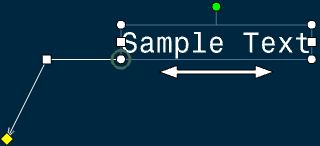
The following figure depicts an annotation with various handles:

Note:
The display of handles for annotations can be configured based on whether the
annotation is selected or its text is being edited. For more information, see
Annotation Handles Display.
The following table shows the representation of handles and pointers associated with
various manipulations:
Annotation Handles Display
You can configure the display of annotation handles based on whether there is
annotation selection or text edition. You can also configure the transparency
level of the handles depending on whether the pointer is over a handle or not.
For more information about configuring the display of handles, see .
The following table lists the default values for display of handles:
| Handle |
Representation |
Selection |
Text Edition |
|
Rotation
|

|
Displayed |
Displayed |
|
Stretch text
|

|
Displayed |
Displayed |
|
Resize text
|

|
Displayed |
Displayed |
|
Slide Text
|

|
Displayed |
Not displayed |
|
Resize leader attachment
|

|
Displayed |
Not displayed |
|
Move leader anchor point
|

|
Displayed |
Not displayed |
|
Move leader
|

|
Displayed |
Not displayed |
|
Indicate a moveable datum
|

|
Displayed |
Displayed |
The display of handles can be different depending on whether the pointer is over
a handle or not, as explained in the following table:
| When the pointer is... |
What happens... |
How it looks |
| not over any annotation handle |
handle's representation is transparent. |

|
| over the annotation representation itself |
handle's representation is transparent,
but the annotation text box is highlighted. |

|
| over a handle |
handle's representation becomes solid. |

|
Notes:
- The transparency level of handles representation changes between the
transparency level defined in the options and the solid state
depending on whether the pointer is over a handle or not.
- All the handles get hidden as you click on any one of them. They
remain hidden throughout the manipulation process and become visible
again as the manipulation ends.
Annotation Rotation
You can quickly rotate an annotation using a rotation handle while using the
Select command.
The rotation handle is at the center-top of the object's frame.

During rotation manipulation, a frame is displayed to represent the transient
position of the object.
Handles are hidden as you click to rotate.

Annotation Positioning
You can position an annotation with respect to another annotation on a
specific point (attachment point) at its anchor position.
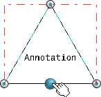
The attachment points are visualized when you move the pointer over the reference
annotation during the annotation creation. The nearest attachment point is
highlighted in blue indicating that the annotation can be positioned on it if that
point is selected. Once it is selected, the annotation is positioned on it and all
the attachment points disappear. Note:
You can select the attachment points of an
annotation during creation of a positional link. Select the Create
text on attachment points only check box from
section, under Annotation Creation.
The following types of annotations can be positioned associatively:
The following types of annotations can be used in associative annotation positioning:
- Text
- Datum Target
- Datum Feature
- Coordinate Dimensions
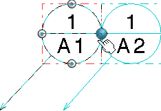
The attachment points where an associative position can be created depend on the
frame type of the annotation. The following table depicts some of the frame types of
annotations and their attachment points:
Note:
The attachment points for all fixed frames are on the frame even if the frame
is smaller than the annotation.
Annotation Placement on Another Annotation
When placing an annotation on an existing annotation, you can choose an
attachment point and position the annotation. You can also change the annotation
position by snapping the annotation to a different attachment point.
Snapping of an annotation can be done during the creation of an annotation or
during the creation of an associative positional link, using one of the
following commands:
- Text
- Text with Leader
- Datum Feature
- Datum Target
When positioning an annotation on an existing annotation:
- If an attachment point is selected, it is highlighted to show that the
annotation is positioned at that point. If the annotation has a leader,
it is removed.
- The attachment point can be moved interactively. Its position is snapped
to the closest attachment point of the reference annotation.
- The positional and orientation links are created between both the
annotations.
- The anchor point of the positioned annotation is also managed to make
sure that it is properly aligned with the reference annotation according
to the attachment point.
- If no attachment point is selected, the annotation is positioned at the
indicated location, without snapping to any attachment point. However,
while positioning the annotation leader, the orientation of the leader
can be snapped on the privileged direction.
When positioning an annotation with a leader on an existing annotation:
- The leader is removed as soon as the target annotation is selected.
- If an annotation with a leader containing an attribute link or a link template is instantiated and positioned
on an existing annotation, its leader is removed but the link is
resolved.
When creating a positional link between annotations, the following contextual
commands are available:
- Positional Link > Create
- Positional Link > Replace
Note:
The existing leader is not removed if you link an annotation with other
annotation using the above contextual commands.
Annotation Orientation
When creating an annotation or instantiating an annotation, you can change the
angle of the annotation to 90deg. To do this, hold Alt
while clicking in the sheet to position the annotation. If
Alt is released, the annotation angle is reset to its
previous value.
Annotation Lock
You can lock annotations for editing using a dedicated option available on
various annotations. You can also control the access to this option thereby making
it impossible to unlock the locked annotations.
To lock an annotation to prevent its modification or editing, right-click it and
select Properties > Text tab and select the
Lock Editing check box and click
OK. For more information, see Text Tab.
The following annotations can be locked for editing:
- Texts (including 2D component instances)
Modifiable text of
a 2D component has the same Lock Editing value
(locked or unlocked) as that of the reference text in the 2D component.
However, you can change this value in the 2D component instance, if
required.
- View texts
- Datum feature
- Datum target
- Geometrical tolerance
- Roughness symbol
- Welding symbol
When you right-click an annotation and select Properties >
Text tab and select the Lock Editing check
box, the annotation is locked. Afterward, it is impossible to edit the annotation
character string by any means, that is using the context menu, double-clicking the annotation, etc. In this case, the following actions take
place:
- The Text Editor dialog box does not appear.
- If you try to edit the annotation, an error tooltip appears informing that
the editing of the annotation has been locked and it can be unlocked using
the Properties > Text tab.
- If the access to lock editing property has been disabled, the message
appears informing that the editing has been locked and only an administrator
can unlock it.
- The Replace is not available in the
Replace dialog box or in the
Find dialog box, when you press
Ctrl+H when a string to be replaced has been
identified in a locked annotation.
Texts in a Table Cell
You can lock text editing in a table cell.
When you add a cell to a table, the newly added cell is initialized with the
Lock Editing value of other cells as per the
following rules:
- When you add a row, the Lock Editing value is
copied from the upper cell.
- When you add a column, the Lock Editing value is
copied from the left cell.
In general, when you copy and paste an annotation, the pasted annotation gets
the Lock Editing value as that of the copied annotation.
|


