Creating Joggles

You can create joggles.

A joggle is a feature that causes the main feature to be locally deformed. It cannot exist alone: it is always defined on a surfacic flange or a web.


Before you begin: Create a web with a surfacic flange and a plane.
See Also
About Joggles
Joggle Tables
In the Knowledge Base
In which cases is it impossible to create a joggle on a surfacic flange?
  1. From the Model section of the action bar, click Joggle .
  2. Select the support.

    To create joggles on a closed surfacic flange, you need to create two half-surfacic flanges first with the Bend Extremities type defined as Minimum.

    Tip: You can click the arrow at the right side of the Support box to display a schema showing the joggle parameters to be defined.
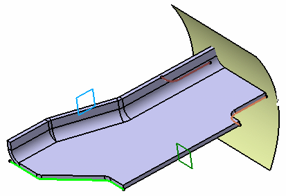
  3. Choose the joggle plane.
    The blue curve defines the boundary of the web and the yellow line is a preview of the joggle.

    The vectors show you the joggle directions:

    • The vector on the surfacic flange or the web support determines the depth direction.
    • The vector on the joggle plane determines the side on which the joggle is to be created.


    Note: If there are several intersections between the surfacic flange or the web and the plane, the closest intersection is chosen.
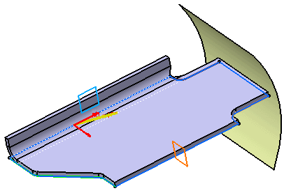
  4. To define the position of the plane, select one of the following options:
    OptionDescription
    Start Defines the plane as the start of the joggle.
    End Defines the plane as the end of the joggle. By default, the plane as end of joggle option is selected.
  5. Define the offset type.
    OptionDescription
    Depth Defines a gap between the support surface and the joggle offset surface.

    You can reverse the depth direction either by clicking Depth Direction in the dialog box or the arrow in the 3D area.

    Surface Creates an offset surface.

    For more information, see Creating Joggles by Selecting Offset Surfaces.

    For more information, see Creating Joggles by Selecting Offset Surfaces.

  6. Optional: To define a compensation, select the Apply compensation check box.
    For more information, see Compensations on a Twin Joggle.
  7. Define the following parameters:
    OptionDescription
    Depth Gap between the support surface and the joggle offset surface.
    Runout Length of the joggle area.
    Clearance Gap between the joggle plane and the end of the joggle area.
    Start Radius Radius value at the start of the joggle area.
    End Radius Radius value at the end of the joggle area.

    If you modify the Depth, the Runout adjusts automatically, thanks to the formula applied to the runout parameters. If you do not want it to be adjusted automatically, right-click the Runout box, select Formula > Deactivate in the context menu.

  8. Click OK.