Defining Beam Sections | |||
| |||
-
From the Finite Elements section of the action
bar, click Beam Section
 .
.
- Optional: Enter a descriptive Name.
- Select a geometry support.
A beam section must be applied to one or more lines. The lines must exist within the PartBody container; sketch lines are not valid supports. You can also use geometry from an ordered geometric set.
You can also assign local beam sections using the tools in the context toolbar. Click
 to assign a beam property to a group of edges, or click
  to assign a beam property to multiple edges that you select using the propagation method. If the support you select already has a material assigned to it, the Material field displays the material that is applied to the support.
 - Optional: If no material is assigned, or if you want to override the existing material assignment, do the following:
- Click
 .The Material Palette appears.
 - Search for the material you want to assign, and click it.
- Click OK to close the Material Palette.
The Material field displays the newly applied material. - Click
- Optional: Choose Integrate section before analysis when numerical integration over the section is not required. The cross-section properties are calculated only once, and all section computations during the simulation are performed in terms of the precomputed values.
- Select a beam profile that defines the cross-section of the beam. For more information, see About Beam Profiles.
- Select a material Behavior that will be used in the simulation.
- Select an Orientation method.
- Align to geometry: Select the Orientation geometry selection box to activate it; and select a point, a line, or a face to orient
the beam section.
The approximate n1-axis direction is defined by the selected point, line, or face as follows:
- Point: the normal from t (the beam axis) to the selected point.
- Linear edge: the direction of the line.
- Plane or planar surface: the normal to the plane or surface.
- Rotate about beam axis: Use the manipulator to orient the beam section about the Z-axis. The local X-axis of the manipulator is considered the approximate n1-axis. If multiple supports are selected, the manipulator is available on the last selection and all supports are rendered together.
You can orient the beams using either the n1–direction or the n2–direction by selecting 1-Axis or 2-Axis from the Define cross section axis options.
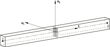
The orientation is defined by a local right-hand coordinate system (t, n1, n2). The t-axis is along the axis of the beam in the direction that the beam geometry was created, as shown in the figure below.
The n2-axis is the cross product of t x n1; the actual n1-axis—which might differ from the approximate axis direction—is n2 x t.
Verify that the image of the beam section on the model is oriented correctly.
- Align to geometry: Select the Orientation geometry selection box to activate it; and select a point, a line, or a face to orient
the beam section.
- Optional:
Specify an offset for the origin of the beam cross-section. Your selections for the
Integrate section before analysis and
Orientation options determine which translational and rotational
options are available for positioning and orienting beams.
- If Integrate section before analysis is selected and the orientation mode is Align to geometry, you can translate the beam cross section origin in the X- and Y-directions.
- If Integrate section before analysis is selected and the orientation mode is Rotate about beam axis, you can translate the beam cross section origin in the X- and Y-directions and rotate about the Z-axis in the triad.
- If Integrate section before analysis is clear and the orientation mode is Rotate about beam axis, you can rotate about the Z-axis in the triad only. You cannot translate the origin.
- Enter the Beam Section options. For more information, see Beam Section Options.
- Click OK.A 3D representation of the selected beam profile appears on the selected support.