From the Concept section of the Flow optimization
assistant panel, select Generate design.
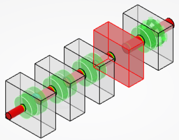
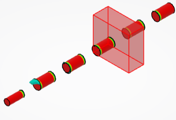
By default, all zones are selected for the generation. The automatic extraction of
geometry is based on the normalized velocity field.
Clear the volumes that you do not want to generate.
Transition zones of selected volumes are highlighted in green and nonselected
zones are highlighted in red.
Note:
If you clear all check boxes, Generate and
Preview are not available.
Define the frame index.
Define the cutting value.
Specify the axial transition value.
Optional: Enter a descriptive name.
Optional:
In the Interface fitting options frame, define the following
parameters:
Axial transition
Radial transition
Sensitivity
Roundness transition
You can manage these parameters for all interface faces or interface per interface.
:
inlet or outlet
:
interface
:
sensitivity. This corresponds to the angle of the shape that connects the interface with
the optimization result.
:
optimization result
:
transition roundness. It modifies the roundness of the connection between the
optimization result and the inlet or outlet. The higher the value, the smoother the
result.
:
transition distance. It modifies the length of the optimization result area that can be
modified. By default, this corresponds to 10 times the size of the mesh and is global to
both inlets and outlets.
Specify the output type:
Option
Description
Subdivision surface
Generates an exact subdivision surface.
Tesselated surface
Generates a polyhedral surface.
Define the reconstruction output for the exact subdivision surface:
Option
Description
Hybrid subdivision
Generates a hybrid subdivision surface.
Match
Generates match features. Datum features are no longer generated. This
methodology reuses more geometry from the design space.
Define the targeted number of faces for the subdivision surface.
Option
Description
Automatic
The number of faces is automatically computed.
Global target
Define a targeted number of faces for the whole subdivision. This is the default
behavior.
Axial/Radial target
Define the number of axial faces along the pipe and radial faces around the
pipe.
Optional: To display the possible designs in several views, click
Multiple viewer and do the following:
In the Multiview layout list, choose the number of frames to
be displayed.
You can modify the frame index and cutting value.
Select the layout and click Choose.
Optional: To define the view, do the following:
Specify whether you want to preview the velocity on the whole shape or on the
optimized designs only, or whether you do not want to preview it.
To show the transparency on the representation of the design space, clear
Transparent design area.
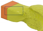
To hide the display of the axial transition distance with a plane, select
Interface fitting area.
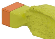
In the Generate design dialog box, click
Preview to display the generated shape.
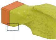
Transition distance: 50mm
Transition
Roundness: 50%
Sensitivity:
0.5
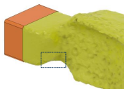
Optional: Modify the parameters.
Transition distance: 100mm
Transition
Roundness: 50%
Sensitivity:
0.5
Transition distance: 50mm
Transition
Roundness: 0%
Sensitivity:
0.5
Transition distance: 50mm
Transition
Roundness: 50%
Sensitivity:
1
Click Generate.
When the design generation is successful, a panel informs you about the number
of faces in the reconstructed shape. It also lets you generate more concepts or discard
the computation.
 Note: If you clear all check boxes, Generate and Preview are not available.
 :
inlet or outlet
:
inlet or outlet  :
interface
:
interface :
sensitivity. This corresponds to the angle of the shape that connects the interface with
the optimization result.
:
sensitivity. This corresponds to the angle of the shape that connects the interface with
the optimization result. :
optimization result
:
optimization result :
transition roundness. It modifies the roundness of the connection between the
optimization result and the inlet or outlet. The higher the value, the smoother the
result.
:
transition roundness. It modifies the roundness of the connection between the
optimization result and the inlet or outlet. The higher the value, the smoother the
result. :
transition distance. It modifies the length of the optimization result area that can be
modified. By default, this corresponds to 10 times the size of the mesh and is global to
both inlets and outlets.
:
transition distance. It modifies the length of the optimization result area that can be
modified. By default, this corresponds to 10 times the size of the mesh and is global to
both inlets and outlets.