-
Open the Sketcher Alignment app for vertical alignment design. Either:
- Double-click an existing vertical alignment in the tree or
- Create a vertical alignment.
- From the tree or in the work area, select a vertical alignment instantiated in an alignment node under an alignment set.
Alternatively, select the terrain under the vertical alignment node in the tree. - Optional: In the Alignment options section of the Alignment assistant, select Additional points in table check box to add additional points in the 2D layout view with a regular spacing based on minor stationing interval.
- From the Alignment section of the action bar, select Table
 . . The 2D Layout for 3D Design
app opens.
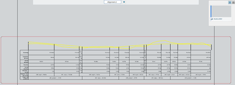
A 2D layout view that contains a sheet and an auxiliary view is created. The view contains
the alignment table, the vertical sketch geometry and the terrain reference curve. The
scale of the view is automatically computed based on the sheet size and alignment length
to fit the sheet format. - Optional:
Filter the table content by customizing the
TableFilter.xsl sample
file provided along with Civil Engineering 3D Design in win_b64\resources\Civil\Alignment. For more
information, see Procedure to customize the Export Report
command.
- Optional: From 2D Layout for 3D Design, generate a drafting of the current alignment 2D layout view provided that you have the required license.
|