Creating the Bridge Layout Distribution | |||||
|
| ||||
-
From the Civil Engineering section of the action bar,
click Bridge Design Assistant
 .
.
-
Select a bridge profile:
Profile Description 
A Simple Bridge will be created with the possibility to edit each span length and each support position individually. The pattern command is not available for the edition of a simple bridge.
In a simple bridge, the reference station to define support distribution can be an intersection station or a start station.
- If the reference station is an intersection station,
- With an even number of supports (such as 2, or 4 supports), there is no support at the intersection station.
- With an odd number of supports (such as 3, or 5 supports), the support at the intersection station is generated.
- Typically, an intersection station can be the alignment of the road or highway to cross.
- If the reference station is a start station, the support distribution is similar to that of the custom bridge.
You can input a text to define the support distribution.
This type of bridge is suitable for designing a cross-road or cross-highway bridge with a small number of supports.

A Custom Bridge is initialized on the basis of counting mode. The pattern command is available for the edition of the support distribution.
You can input a text to define the support distribution.
- If the reference station is an intersection station,
-
In the work area,
select the following elements:
-
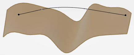
An alignment or a curve (3D alignment) in the 3D area:
- A curvilinear pattern is generated from the selected curve.
- If the bridge start and end points are automatically detected on the alignment, they will be set. Otherwise, default ones are proposed, and you can edit them.
-
A terrain.
The selected terrain can be a plane, a surface, a mesh, or a polyhedral feature. If the selected curve is an alignment to which the terrain is associated, the terrain is selected automatically and a default bridge skeleton is automatically generated.
You can split the terrain around the bridge area. For more information, see Using a Bounding Box. You can do the following:
- Select a terrain in the Bridge Design Assistant and it is automatically cut and re by a bounding box. The terrain is renamed Clipping of Terrain xxx in the Terrain box in the panel and it is aggregated in the Bridge Set in the tree.
- From the App Options panel, click
 to
enable/disable the split of the terrain. By default, it is split.
to
enable/disable the split of the terrain. By default, it is split. - The terrain cannot be split when you select a plane or a triangulate surface.
- For a simple bridge, if you use the Intersection Station mode, the split is made along the alignment's length. You can choose an anchor point or Start Section for the bridge, and both the bounding box and the split terrain are redefined.
- For a custom bridge, if you modify the bridge's extremities, the terrain split updates. If there is no start point, an extremity point is created automatically and selected for the split.
- Edit the feature Clipping of Terrain xxx by clicking
 next to the
feature name in Bridge Design Assistant.
next to the
feature name in Bridge Design Assistant. - Edit the bounding box by clicking
 next to the feature
name in the Split command.
next to the feature
name in the Split command.
The schematic layout of the bridge is now created. In the 3D area, the support representations (deck, supports, and abutments) and the distance between piers are visible:
To delete the selected elements in the Start/End Station box, click the Clear Selection contextual command.
The Bridge Set node appears in the tree. This geometrical set contains a set of geometric features corresponding to the layout representation of the deck and supports.
You can read the number of supports in the Bridge Design Assistant. This number includes the start support and the end support.
The Number of Supports box changes according to the pattern definition:
- For custom bridges, if the pattern is initialized with only one group defined by the Number of Supports, you can modify the number of supports by increasing or decreasing its number, if the pattern contains only one group.
- For simple bridges, the Number of Supports box is
always editable.
Supports are added externally on either side of the bridge to satisfy the new distribution if you have changed the layout with Number of Supports. Otherwise, supports are added between the start and end of the bridge only if: the start and end are snapped to the user-defined points and, you have applied this change with Number of Supports. As a result, the span distribution will be updated according to this change.
-
The Start/End Station for custom bridges: You can create/edit a 3D alignment point
or a GSD point on curve.
When using the Alignment Point command, you can pick a 3D alignment in the 3D area, this picked position is automatically set and highlighted. Then you can click the alignment to move the point. If you create an alignment 3D point, this point is not created on the horizontal alignment.
You can arrange the alignment points without switching into the alignment sketch, by choosing 3D alignment points:
- If the picking point lies between a Start station and an End station defined in alignment, then the bridge starts and ends in between.
- Otherwise, the bridge start and end stations are automatically created from the picking point with a default curvilinear distance.
If the alignment is the 3D alignment feature, the created points are alignment point features. The start and end stations are automatically entered respectively as Start of Bridge, and Start of Ground. Otherwise, the created points are GSD point on curve.
If the distance of the picking point to the alignment extremity is less than the above defined distance, then the corresponding start or end station are this alignment extremity.
-
Reference Station (Intersection/Start Station) for simple bridges.
- You can choose either Intersection Station or Start Station as the reference Station for support distribution definition.
- By default, the picking point on the bridge alignment is proposed as the reference station.
- You can select a point or a curve as reference station. If it is a curve, it must intersect with the bridge alignment horizontally. Typically, you can select the alignment of the road or highway to cross as the intersection station.
-
An alignment or a curve (3D alignment) in the 3D area:
-
Optional: To move the bridge globally, do either of the following:
- For a simple bridge,
- Edit its reference station, which can be an intersection station or a start station.
- Or select a middle support and use the ruler.
- For a custom bridge, edit the start station.

- For a simple bridge,
-
Optional: To edit the support position and span length locally, for simple
bridges, do either of the following:
-
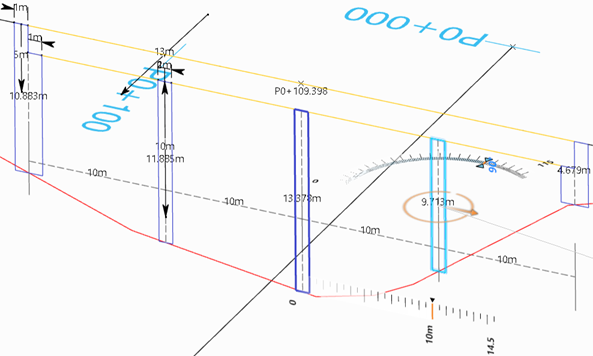
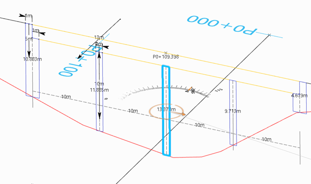
Select a support. If it is not defined by a user-defined point, a ruler is
displayed, allowing you to choose the distance between the supports. To specify
offsets, the ruler has a grab handle triangle. The ruler also has one editable number
representing the current value. The stepping of the value depends on the scale. Note
that the ruler is not displayed if the support position is defined on a user-defined
point.
-
Edit the Default Span Length, for simple bridges, in the
parameter of the same name.
When you change this parameter, a confirmation message is displayed.
Note: If the user-defined feature (UDF) of a pier shares the same height parameter, it is automatically set equal to the bridge Support Height parameter in the Bridge Design Assistant.
-
Select a support. If it is not defined by a user-defined point, a ruler is
displayed, allowing you to choose the distance between the supports. To specify
offsets, the ruler has a grab handle triangle. The ruler also has one editable number
representing the current value. The stepping of the value depends on the scale. Note
that the ruler is not displayed if the support position is defined on a user-defined
point.
-
To display the detailed information about supports, for simple and custom bridges,
click Display detailed support distribution
 .
.
The Span Distribution box contains the number of spans, with their curvilinear distance.
By default, Span Distribution is set to appear. If not, click
and the
Span Distribution line appears after Default Span
Length for simple bridges, and after Number of
Supports for custom bridges. When this line appears, support distribution
is computed and displayed in the 3D area.Click
again to hide the
line. -
To reinitialize the bridge distribution, edit the text in the Span
Distribution box, for example:
30m+2x40m+33.5mor3x3000.The inputs of previous distribution are removed, except the reference station for simple bridges and the start station for custom bridges, which are mandatory.
You can continue to edit the support distribution with all the available tools, and the support distribution text will be updated in its editor.
The general format of the distribution text is described below:
n1 x L1 + n2 x L2 + n3 x L3with:- "ni" (optional): Is the number of supports of the group "i". If the number of supports of this group is equal to 1, it can be omitted.
- "Li" (mandatory): Is the span length of this same group. It can be associated to a unit. If it does not have a unit, the unit set in is used. If a unit is used to define a length, the same unit must be used for all lengths.
The distribution text is converted into a pattern definition:
- For simple bridges:
- The text distribution relies on the same pattern used by the simple bridge.
- If the reference station is Start Station, the distribution is converted from the start station. The default span is used to define the span distance from the start station, for example: 1e+0006mm, in which "ie" means that the default span length is used for all the spans.
- If the reference station is Intersection Station and the total number of supports is even, the intersection station is positioned at the center of the middle span, on which additional supports can be inserted.
- If the reference station is Intersection Station and the total number of supports is odd, the intersection station is positioned at the center of the middle support, around which additional supports can be inserted.
- If the Start and End supports have been defined and the Deck is hyperstatic, there is only one deck and its length cannot be modified.
- If the Start and End supports have not been defined and the Deck is isostatic, there are several decks and the bridge layout can be modified.
- For custom bridges:
- The text distribution relies on the same pattern used by the custom bridge.
- When you initialize the bridge layout, you can choose different distribution
modes.
Distribution Mode Description Count 
Only count value modification and only one group are allowed. It impacts on the number of supports. Spacing 
Only spacing value modification and only one group are allowed. Count and Spacing 
Count and Spacing values modification is allowed and several groups can be created. If a pattern end point is specified, a Limit Spacing option is available to shift the Pattern distribution. Note: If the current mode is Count and spacing, it can contain as many groups as needed, separated by the plus sign. All the groups created are in the Count and spacing mode. There cannot be several groups with different modes. If you change the definition of one group, the text editor is grayed out. - If the Span Distribution is 4x10m, you obtain one group in the Curvilinear pattern. If you change the span distribution into 4x10m + 3x15m for example, you obtain two groups. Then the Number of Supports box is grayed out because the algorithm cannot choose either of the groups to edit.
- If you edit the Count value, the number of supports varies according to this new information and the span distance adjusts itself.
- The bridge start point is kept, and the end point is removed, because the end limit is automatically computed by the distribution text.
- Click
 to start the
pattern for more precise edition.
to start the
pattern for more precise edition.
For simple and custom bridges, when you input a span distribution text, the support distribution is reinitialized with this text. Then you can continue to edit the span distribution.
-
Optional: To orient the support globally, for simple bridges, do the
following:
-
Select the alignment in the 3D area.
Notes:
For Custom Bridge, the supports are always perpendicular to bridge alignment. You cannot orient the support.
For Simple Bridge, you can modify the supports' orientation.
If nothing is selected, the Robot is automatically snapped to the intersection station of the support. By default, the skew angle is set to 90 degrees.

-
Click the manipulator arc (orange) and rotate the skew angle along the selected
alignment or set the exact angle value using the displayed ruler or by entering a
value in the angle editor. You can also edit the skew angle directly in the
Support Orientation parameter editor of the dialog box.
The orientation of all the supports is modified.
-
To define the orientation by a geometric element (a curve, a straight line or a
plane), click
 .
.
You can select a curve, a straight line, or a plane. When a geometrical element is selected, the parameter value in Global Orientation is replaced by the name of the geometric element. Then you can no longer edit the skew angle.
The orientation is defined for all the supports, except those individually specified in the contextual panel, as explained below.
If all supports have the same orientation, it is better to define it once globally in the 3D area and in the Bridge Design Assistant.
-
Select the alignment in the 3D area.
-
Optional: To orient the support locally, for simple bridges, do the
following:
-
Click and
use the Robot to edit the skew angle locally.
When you select a support that is not locally activated, the Support Orientation contains the Global information. You cannot rotate the global Robot if the support orientation is aligned to a geometry globally.
If you click
 , you can use
the local Robot to edit the skew angle locally. You can select a geometrical element to define the
orientation of this support, in the same way as for the global support orientation.
, you can use
the local Robot to edit the skew angle locally. You can select a geometrical element to define the
orientation of this support, in the same way as for the global support orientation.The skew angle of the selected support is changed accordingly whereas the other supports remain unchanged.
-
Click
-
Edit the pattern.
The command is available for custom bridges only.
-
To change the distribution pattern, click Launch pattern
edition
.
For more information, see Creating a Curvilinear Pattern. You can create complex layout distribution. The figure below shows an irregular support element distribution:

-
To select another pattern, click Display/Hide all available pattern
list
 .
.
All the patterns available to define the support distribution are listed, with the used pattern that is automatically selected.
You can select: a Curvilinear, Linear, or Copy pattern. Make sure that pattern input data is consistent with and valid for bridge design.
Distance preview is only available for curvilinear pattern. The Start Station and End Station boxes are displayed only if the pattern is curvilinear.
-
To change the distribution pattern, click Launch pattern
edition