Create a Simple Transition
In the alignment sketcher, you can create a transition between a line (tangent) and a circular arc, or between two lines, or between a tangent and parameters.
-
To create a transition curve for connecting and transiting the geometry between a
tangent and a circular curve, click Transition
 from the Alignment section of the action bar
and, do the following:
- Select a type of transition to create for the horizontal or vertical alignment.
- Select an Initial geometry: Tangent line at the initial extremity of the transition curve.
- Optional: Specify a Start point (useless when final extremity is defined by a circle).
- Select a circular arc.
- Optional: When initial geometry is a line, select the Reverse option to reverse the orientation of the initial tangent and change the side of the transition curve, and the final tangent orientation (if the geometry is a line). This option is useless when the final extremity is defined by a circle or a point.
- Select the Final geometry: Final extremity of the transition curve (a tangent or an arc). You can select the final curve to create this transition curve between two circles in ove (a circle within another circle).
- Select the Reverse curve side option to define on which side of its initial oriented tangent the curve will turn.
-
To create a transition curve fully parametrized, select an origin point of the
transition, a normal direction (tangent) to orient it and two parameters out of the five
required ones:
- “A” parameter (LxR=A²)
- Transition length (L)
- Arc radius (R)
- Angle at end point
- ShiftingNote:

 Origin point
  Length (L)
 Radius
 Shifting
  End Angle
 In specific cases detailed above, parameters are computed automatically and the parameter frame is grayed out. For example, when the final geometry is a point or an arc, a message appears: no additional parameter is required. And the OK button is available only if all parameters are coherent. If not, an error message is displayed.
When 2D geometry defines totally or partially the final extremity of the transition curve, the final geometry may be:
- Null, or a point, line, or circle. If null, both parameter1 and parameter2 are required.
- A line specifying the tangent at the final extremity of the curve. Then parameter1 is required and cannot be an angle.
- A point or a circle does not require any additional parameter.
Tips: To connect 2 lines with a combination of S-C-S, use the Horizontal Curve  command available in both the contextual bar after selecting an intersection point and
the Sketcher section of the action bar. For more information, see Creating a Horizontal Curve.
command available in both the contextual bar after selecting an intersection point and
the Sketcher section of the action bar. For more information, see Creating a Horizontal Curve.If transition lengths are null, only an arc is created.
Default values are initialized with minimum values based on the current alignment design rules defined for this alignment. If no minimum values can be retrieved from the design rules, L1=0, L2=0 and radius is automatically computed based on the selected lines.
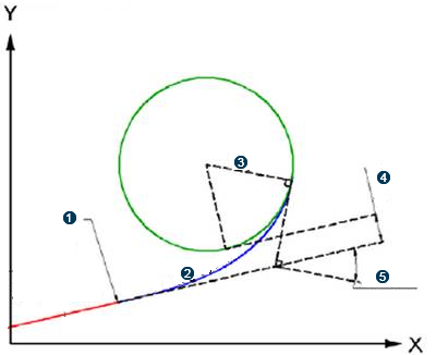
You obtain this configuration: a transition between a tangent and an arc (T-S-C).

 Tangent
  First spiral (transition)
  Curve (arc)
  Second spiral (transition)
  Tangent
 The transition is rigid but movable. Sketcher constraints are supported on transition curve such as coincident, fix, tangency and curvilinear distance. Its curvature begins with zero at the straight section (tangent) and increases linearly with its curve length. Where it meets the circular curve, its curvature becomes equal to that of the latter.
- Optional:
To edit a transition, in the tree, click the transition element and, from the context toolbar, select Edit Geometry Definition
 .
The Transition Definition dialog box opens and lets you edit the parameters of the transition.

