Creating a Horizontal Curve | |||||
|
| ||||
-
To create a transition or curve between two lines, click Horizontal
Curve
 from
the Alignment section of the action bar.
In the Horizontal Curve dialog box, parameters are organized in a tree view. You can specify the Entrance/Exit (in/out speed, spiral type and length, transition length), Curve (radius and superelevation) and Measure (in/out tangent length and curve length) values.
When the Spiral creation
 is chosen in the
Alignment assistant (the background color of the button becomes
blue), you obtain a simple configuration:
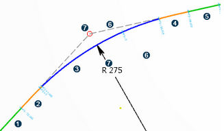
 Tangent
  First spiral
(Clothoid, Cubic parabola, Cosinusoidal, or Sinusoidal)
 Curve (arc)
  Second spiral
(Clothoid, Cubic parabola, Cosinusoidal, or Sinusoidal)
  Tangent
  Construction
lines (tangent at the start and end of the curve).
  Point of
Intersection (PI)Notes:
Point of
Intersection (PI)Notes:- Double-click a curve to obtain information. In the Vertical Curve dialog box, you can change the curve type in the list and select Arc or Parabola.
- You can edit the transition type of the in or out spiral and select either Clothoid, Cubic parabola, Cosinusoidal, Sinusoidal, or None. The None value deletes the feature. For old models with the clothoid type, the geometry is deleted and a new one with the transition type is created.
- You can define horizontal curves and their transitions as well. For example, you can change the speed limit from the Horizontal Curve dialog box and the in/out transition specifications at the same time. The new information is stored at the horizontal alignment level.
-
The In/Out Spiral Length parameter is visible in the Horizontal Curve dialog box. The transition length lays on the spiral. When a formula (automatically added during the spiral creation) exists on the spiral length constraint, the transition length is synchronized with the spiral length. You cannot edit the value of the spiral length.
The transition length and the spiral length can be different. You can withdraw the formula to decouple both lengths, and the spiral parameter becomes editable. For more information, see Road Superelevation and Transition Length Rules.
- In automatic mode, surface Cant/Superelevation sketch law is updated without running the Cant/Superelevation rule and by reading the data stored on the horizontal alignment points. The attainment method rule (business rule) can be executed. You can create a road or railway surface requiring several formulas along the horizontal alignment by using attainment methods (business rules). You can assign these attainment methods to the Building and Civil Resources resource table. Missing rules are reported in specification panel.
- The Minimum/Maximum length of the arc can be customized by the administrator in
the xml resource file named Alignment Design Rules located in
win_b64\startup\Civil\AlignmentDesignRules, from Data Setup. For more information, see Alignment Design Rules Definition.When you create an arc, the Minimum/Maximum length parameters are locked: the value is retrieved from the design rule file and you cannot change these parameters manually in the user interface. You need to edit the xml file called Alignment Design Rules, and located in
startup\Civil\AlignmentDesignRules.When the boundary values are initialized in the xml file, the Min length and Max length parameters appear in the tree under the Arc node with the icon
 . This icon is
displayed when a Minimum/Maximum length of the arc, without formula, has been
defined in the xml file. The Minimum/Maximum length of the arc is locked.
Therefore, its value is updated automatically and you cannot change it unless it
is unlocked.
. This icon is
displayed when a Minimum/Maximum length of the arc, without formula, has been
defined in the xml file. The Minimum/Maximum length of the arc is locked.
Therefore, its value is updated automatically and you cannot change it unless it
is unlocked.Select the Min/Max parameter and click the Unlock contextual command to modify the value of the formula if it exists. When a parameter is unlocked, the following icons appear in the tree:
 when the
Minimum/Maximum length of the arc is unlocked and not restricted. You can
change the length values manually.
 when
a formula has been defined in the xml file. The parameter is unlocked, you can
change the formula manually.
Notes:- More generally, Minimum/Maximum length constraints are created along with arcs, preventing complementary arcs to appear and inconsistent configurations (reverse/intersecting arcs). The constraints are not visualized in the 3D area and the tree. You can only see them in the Sketch Analysis tool. When the arc radius constraint is deleted, Min and Max constraints are not guaranteed on the arc.
- Horizontal alignments created before R2021xFD02 must be upgraded to benefit from this function.
Several simple reverse curves can follow one another and they are independent:

Changes are detected in the Horizontal Curve dialog box:
- If a parameter has been updated automatically (with design rules), this icon
 appears next
to its value in the Curves section. To switch from the
automatic mode to the manual edition mode, you can click the button, and it changes
into:
  .
. - Click the button in front of the spiral constraint to switch from the
Length
 to the
Flatness
 edition.
You can switch any simple corner into dual PI configuration and vice versa with the Switch Curve PI composition
 command of
the context toolbar. To display the command, click on the arc associated with the curve.
The circle radius is not impacted by this change.

In single PI composition, you can drag the PI freely but the construction lines can only be manipulated in the direction of the tangent.
In dual PI composition, in and out construction lines are fixed and the radius of the arc is set to Driven Mode when you manipulate the intermediate construction line. When done, this fixity is removed and the arc radius returns to constrained mode.
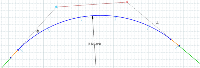
Changes are detected in the Horizontal Curve dialog box:
In dual PI composition, the value of a virtual PI is displayed in Information section: it represents the PI of the curve if it was in a single PI configuration.
-
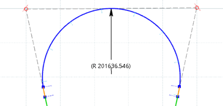
To create a U-Turn curve, do one of the following:
- Draw a composition of three lines turning inwards, then select the centerline and
click Simple Curve Dual PI
 .
.


- You can also create a simple curve with two PIs from two disconnected lines. To do
so, select both lines using the control key on your keyboard and click
Simple Curve Dual PI
 on the context
toolbar. The curve is inserted on the side closest to where you clicked to select the
lines.

 Notes:
- You can create a constraint for the circle to be tangent with the intermediate
construction line located between the two PIs. To do this, select the intermediate
construction line or the circle and click the Simple Curve Dual PI
tangency
 contextual command. You can use the same command to remove the tangency.
- The Switch Curve PI composition
 command
is not available for U-Turn curves.
 - In U-turn configuration, the virtual PI is not displayed in the Horizontal Curve dialog box.
- Draw a composition of three lines turning inwards, then select the centerline and
click Simple Curve Dual PI
-
To create a compound transition or curve (for example, two arcs in the same
transition), do the following:
- Double-click the arc to open the Horizontal Curve dialog box.
-
To add an arc, select Compound in the
Type list. By default, Simple is
selected.
If you switch from a simple to a compound transition, the Composition dialog box appears. You can choose the following parameters:
- In radius: the radius of the first transition curve.
- Out radius: the radius of the last transition curve.
- Intermediate spiral: depending on the compound
transition or curve, different types of spiral are available:
- Clothoid, Sinusoidal, Cosinusoidal, or None for compound.
- Clothoid, Cubic Parabola, Sinusoidal, Cosinusoidal, or None for compound reverse with two spirals
- Clothoid only for compound reverse with one spiral.
- Length:
- ΔR: Imposes a minimum distance between both arcs.
- Curvilinear Distance: Default value. Imposes the transition length as the sum of the transition from both arcs to tangent.
The intermediate spiral is set to clothoid, for example if the option Spiral creation
 is
activated in the Alignment assistant. If it is not
activated, the ΔR parameter is disabled.
To invert radius values, click
 .
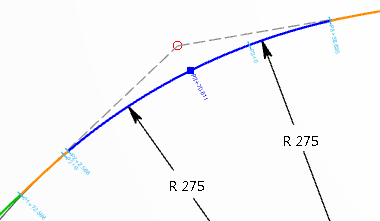
.Curve Parameters are organized in a tree view in the Horizontal Curve dialog box. A second curve appears in this tree. The curve configuration is as follows: Tangent-Spiral-Circle-Circle-Spiral-Tangent.
-
Edit either of the curve radius in the tree directly in the Horizontal Curve dialog box. You obtain a
compound curve containing two curves with a different radius.
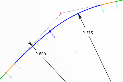
The arc is split in two in the 3D area and an additional node (Curve #2 for example) appears in the dialog box tree.
You can create compound reverse arcs separated by a simple spiral:
Changes are detected in the Horizontal Curve dialog box:
- If a parameter has been updated automatically (with design rules), this icon
 appears next
to its value in the Curves section. To switch from the
automatic mode to the manual edition mode, you can click the button, and it changes
into:
  .
. - Click the button in front of the spiral constraint to switch from the Length
 to the
Flatness
  edition.
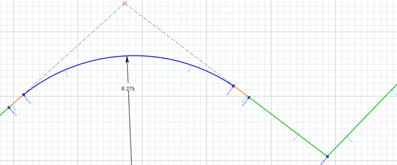
You can also create a compound-reverse configuration with a simple curve followed by two lines. These two lines are orientated in a way that allows corner insertion in the opposite direction of the first one.
-
To create complex arcs with additional circular curves, select an existing curve and
click Add
 in
the Horizontal Curve dialog box.
This button
 is not available when an
intermediary spiral exists.
is not available when an
intermediary spiral exists.The new curve is inserted after the selected one. For example, if you select Curve #2, Curve #3 appears right after Curve #2 in the dialog box's tree and in the 3D area, and both curves have the same radius. In this case, the new curve configuration is Tangent-Spiral-Circle-Circle-Circle-Spiral-Tangent on the alignment profile. Each arc radius can be edited individually. You can create as many arcs as you want. To remove a curve, click
 .
.The Measure section of the dialog box also contains the measures of Curve #3.
Attainment methods let you design successive circular curves with an intermediate spiral, in the road or railway context. The curve configuration can be as follows: Tangent-Spiral-Circle-Spiral-Circle-Spiral-Tangent on both sides of the road surface or on one side of the railway surface. In this case, the change of superelevation rate occurs in the intermediate spiral. If no intermediate spiral exists, the change of superelevation rate occurs in the preceding curve.

Changes are detected in the Horizontal Curve dialog box:
- If a parameter has been updated automatically (with design rules), this icon
 appears next
to its value in the Curves section. To switch from the
automatic mode to the manual edition mode, you can click the button, and it changes
into:
  .
. - Click the button in front of the spiral constraint to switch from the Length
 to the
Flatness
  edition.
- If a parameter has been updated automatically (with design rules), this icon
-
To create a compound oval curve with two arcs linked by a spiral, do the
following:
-
Click the Preferences
 from the
top-right corner of the Alignment assistant panel and select
the Dual PI option.
- Select a line between two curves.
-
Click the Compound Oval Curve Turn
 contextual
command.
Two simple arcs are merged into a compound dual PI configuration: Tangent-Spiral-Circle-Spiral-Circle-Spiral-Tangent. You can manipulate both PIs, modify the radius constraints, and the alignment is still continuous in tangency.The first radius constraint is driving, and the second one, the value of which is in parentheses, is driven.
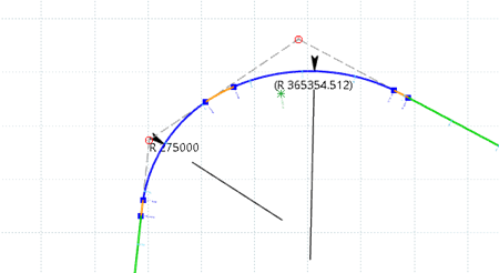
Changes are detected and reflected in the Horizontal Curve dialog box:
- The Type is Compound. You can switch
to the Simple type.
When the initial status is Simple, Compound is available in the Type list when a previous turn exists and is traveled on the opposite way as the current turn.
- The PI stations are displayed in Information section.
- If a parameter has been updated automatically (with design rules), this icon
 appears next
to its value in the Curves section. To switch from the
automatic mode to the manual edition mode, you can click the button, and it changes
into:
  .
. - Click the button in front of the spiral constraint to switch from the
Length
 to the
Flatness
 edition.
 - The contextual command lets you choose the status of the radius constraint between
Driving
 and
Driven
 . Click it
to switch between the two modes. Both radii cannot be measuring or driving,
therefore when one constraint is selected, the other one is impacted
accordingly.
 - The nodes of the intermediate spirals are displayed between Curve #1 and Curve #2 in the Curves section. If a spiral constraint fixes the spiral length, then the flatness information is displayed in the Measure section, and vice versa.
-
Click the Preferences
-
To create a compound transition with reverse arcs separated by two spirals, do the
following:
-
Click the Preferences
 from the
top-right corner of the Alignment assistant panel and select
the Dual spiral option.
- Select a line between two reverse curves.
-
Click the Merge into a reverse turn
 contextual
command.
Two simple turns are merged into a dual reverse spiral configuration: Tangent-Spiral-Circle-Spiral-Spiral-Circle-Spiral-Tangent.

The first radius constraint is driving, and the second one, the value of which is in parentheses, is driven.
There is a common construction line between both Points of Intersection (PIs), allowing the intersection point between the two spirals to move. You can manipulate both PIs, modify the radius constraints, and the alignment is still continuous in tangency.
Single or dual spiral configuration can be specified in the xml file of Data Setup named RoadAlignmentDesign for road and RailwayAlignmentDesign for railway. For more information, see Alignment Design Rules Definition.
Changes are detected and reflected in the Horizontal Curve dialog box:
- The Type is Compound-Reverse. You
can switch to the Simple type.
When the initial status is Simple, Compound-Reverse is available in the Type list when a previous turn exists and is traveled on the opposite way as the current turn.
- The PI stations of the arcs are displayed in Information section.
- If a parameter has been updated automatically (with design rules), this icon
 appears next
to its value in the Curves section. To switch from the
automatic mode to the manual edition mode, you can click the button, and it changes
into:
  .
. - Click the button in front of the spiral constraint to switch from the
Length
 to the
Flatness
 edition.
 - The contextual command lets you choose the status of the radius constraint between
Driving
 and
Driven
 . Click it
to switch between the two modes. Both radii cannot be measuring or driving,
therefore when one constraint is selected, the other one is impacted accordingly.
Please see the image above.
 - The nodes of the intermediate spirals are displayed between Curve #1 and Curve #2 in the Curves section. If a spiral constraint fixes the spiral length, then the flatness information is displayed in the Measure section, and vice versa.
- Two spiral flatness values are displayed in the Measure section.
To edit the curve or spiral parameters in the Horizontal Curve dialog box, double-click any geometric element belonging to the reverse curve.
-
Click the Preferences
-
Create points using one of the following point commands:
Option Description Point 
To create a point by positioning it on the sketcher plane. Point on Alignment 
To create a point on the alignment.
When you double-click a point on the alignment in the tree or 3D area, the Alignment Point dialog box opens and you can see:
- The Stationing definition of the selected point. You can edit it. A Stationing feature appears in the tree under the Component Specifications node.
- After you pick an alignment in the 3D area, the picked position is automatically proposed as the initial point, with its stationing definition displayed on the stationing editor. The point is also highlighted in the 3D area.
- After editing the stationing definition in its editor, its new position is automatically highlighted.
- The type of the 3D point, for example Start of Bridge or Start of Ground. You can define/edit it if required. The same typing is added to the 3D point on the 3D alignment. A Type feature appears in the tree under the Component Specifications node.
Important: If you move this point with the mouse, the point might not remain on the alignment entities. But if you edit the point stationing value in the Point on Alignment command, you can move it to the required position. Point by Offset 
To create a point by offset. Equidistant Points 
To create one or more equidistant points. Point by 3D Point Projection 
To project 3D points on a sketcher plane. Switch Points 
To convert points into alignment points and reversely. Notes: The Alignment Point dialog box lets you:- Set your Parameters:
- Start Point/End Point (the last point of the alignment is automatically defined as the endpoint)
- Stationing
- Label
- Index
- Speed
- Category
- Superelevation
- Type: Select a semantic type, Bridge, Dam, Ground (for natural terrain level) or Tunnel, for alignment points.
- Select the parameters (Radius/Gradient table) driven by the Design rules stored in Data Setup.
For more information about design rules, see Design Rules.
-
To edit a horizontal curve, double-click the arc or transition, the point of
intersection or the construction lines to open the Horizontal Curve
dialog box. For more information about these objects, see the image in Step 1.
Tips: -
You can edit the intersection point by clicking
 on the context toolbar.
Curve Widening and Ratio on Inner Edge can be read or overloaded in the Horizontal Curve dialog box. By default, they are automatically valuated.
-
To edit the simple, compound, and reverse curves one after the other, use the navigation arrows

 on each side
of the Name box in the Horizontal
Curve dialog box. You can navigate through the curves, following the
trajectory of the alignment. The alignment must contain at least a curve and a
tangent.
on each side
of the Name box in the Horizontal
Curve dialog box. You can navigate through the curves, following the
trajectory of the alignment. The alignment must contain at least a curve and a
tangent.When you double-click a tangent, a PI, a spiral, or a curve, the Vertical Curve dialog box appears, and navigation arrows are available. When you click an arrow, the display automatically switches on the previous or next curve and places the current curve, with its tangents and spiral, arcs, at the center of the 3D area. Moreover, the dialog box is updated with the next curve information.
Each curve is modified independently from the others. No need to validate and to close the dialog box after each curve edition. If you click Cancel, the modifications made on all the curves are canceled.
Notes:- It is recommended to clear the Distorted scale option, otherwise the zoom on the curve cannot occur during navigation.
- A reverse or a compound curve contains more than one curve. It is, however, considered as a unique curve during navigation. In this situation, more than one curve is zoomed in.
- The left
 or
the right
  arrow is disabled when:
- you get to the first or last corner of the alignment.
- there is a corner with only a point, without any spiral and tangent.
-
- To overload the Curve Widening or the Ratio on Inner Edge, set them to false and, enter the required length.