Procedure for Designing a Reference Object Type

You can select among three types of object types. To design a reference object type certain elements are mandatory and other elements are optional. For maintenance purposes, design your user defined feature and your engineering template in the same numerical model.

A reference object type must contain a user feature (feature-based design), an engineering template or a physical product (product-based design), and a medium icon (thumbnail). Optionally, it can contain a small icon, a documentation guide and a design table. In the following procedure, you will create a reference rectangular crosshead.

The stages in this procedure are as follows:

Context:

You already designed a bridge. You have several crossheads with the same configuration (two in the following example) and you want to create one parametric object to design these crossheads. You also want the reference crosshead object to be reused in another project


The above figure is a typical example of a product structure.

Determine the Crosshead Specifications

Prior to design the input geometry to design the reference crosshead, you determine the accurate specifications of the crosshead you envision.

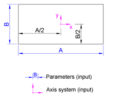
  1. Create plane view specifications


  2. Create crosshead elevation
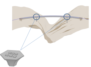

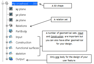
Create a User Feature (feature- based design)

Creating a user feature involves selecting specific geometrical inputs around which your model should be built. You must create an axis system at a minimum and can also create other axis systems, surfaces, planes. You can add Numerical parameters, Boolean parameters, list parameters to handle dimensions or for displaying certain portions of your model.

  1. Create a user feature with a body as output.
  2. Open your Output body and select all elements.
  3. Right-click your selection in the tree, and select Insert In New in the context menu.
  4. Optional: From the Tools section of the action bar, click User Feature .
    The User Feature Definition dialog box appears.
  5. Enter the user feature name, and select the user feature inputs in the tree:
    1. Select the Relation set.
    2. Select the Construction geometrical set.
    3. Select the Functional surfaces geometrical set

      Do not select the geometrical set inputs (inputs tab)

  6. Optional: In the Input tab, rename the first input axis in Base Axis System. This is to comply with the storage rules for object information in civil engineering apps.
  7. For the other inputs, consider you instantiate the object type by using functional surfaces of another object type. Rename your inputs accordingly that is with the same naming.
  8. In the Meta Inputs tab, associate your inputs to the relevant objects. If the naming of the inputs of your object type is consistent with the naming of the semantic geometry of the instantiated object, you will only have to select the input object during instantiation.
  9. Publish all the parameters related to the definition of your object type

Create an engineering template and a reference

For your object design, you need to choose certain geometrical inputs around which your model should be built. You must create as a minimum an axis system but you can also create other axis systems, surfaces, planes, curves, points. You can define numerical parameters, Boolean parameters, list parameters to handle dimensions or to display certain parts of your model.

See Create an engineering template (product- based design)

Create a Thumbnail Icon

You must create a medium icon representing the object type to be displayed in the Search panel. Create the icon to associate it to the object type you are creating.

See Create a Thumbnail Icon.