Configure the AR Experience
You can access AR through a dedicated command. Once AR is configured, you can move your device around a printed marker and see your virtual object on top of it.
-
From the AR-VR section of the action bar, click iV Magic Window
 . .
- If you have a video camera, then the camera starts streaming images which are displayed on the background of the current 3D scene. You need to print a marker to display the 3D scene in the desired position.
- Otherwise, the AR experience uses a still image with a marker as a background.
- In the AR Configuration dialog box, click
 to access configuration options. to access configuration options. -
In the Source area, select the source of the image to be augmented.
| Option | Description |
|---|
| Live camera |
A camera, such as a web cam. If there is more than one available camera, use
the list to select the camera to be used. |
| Video file |
A pre-recorded video footage. Click the ... button then
browse your file tree to select a file. You can also select one or more still images
to be successively displayed, showing a virtual object in many different real life
situations. |
Note:
On some devices such as the Surface Pro 2, on Windows 8.1 Pro, a conflict might occur between
the two embedded cameras and the external USB camera. To use an external camera
instead of the embedded ones, right-click .
- In the Camera Calibration area, specify the parameters of the camera selected in the Source area.
For more information, see Calibrate the Camera. -
In the Rendering area, select the options to be used for
rendering.
| Option | Description |
|---|
| Mirror |
Instead of displaying what the camera sees, this option displays your
reflection surrounded by virtual objects. For example, moving the marker to the
right moves the virtual object in the same direction. This option is especially
useful when facing the display screen and the camera at the same time. |
| Render background |
Renders the image to be augmented as a background. The background can be
deactivated to make the marker act as a tangible interface in a fully virtual world.
By default, this option is selected. |
-
In the Marker area,
use the list to select a predefined marker to detect in the current image, or click More... to select a user-defined one.
A marker is a picture which can be detected in real-time using image-processing techniques. Markers can be as simple as black and white bar codes, or as complex as a photograph.
Pre-defined markers are provided in C:\Program Files\Dassault
Systemes\B424\win_b64\resources\graphic\ARMarkers - Bitmap images to be used by the app
- PDF files to be printed by the user.
The Efficiency box indicates the isa global grade given to the marker to help you compare markers.
- In the Marker width box, indicate the physical size of the marker in millimeters.
It is important to accurately measure the smallest side of your printed marker with a ruler to ensure a stable tracking and a realistic model scaling. - In the 3D Model area, define the Scale to be used.
This allows you to view models at a scale different than 1:1 which is especially useful when you need to make an entire car fit in the palm of your hand, for example. - In the Position box, define the offsets in millimeters to adjust the position of the virtual model relative to the center of the marker.
-
In the Orientation (deg) box, define the angles of the model
relative to the marker frame.
The angles must be set in degrees and must correspond to rotations around x, y, and
z axes.
- In the Tracking area, specify the tracking algorithm to be used.
This algorithm is always a compromise between speed and accuracy: - The most accurate algorithm handles partial occlusions of the marker.
- The least accurate algorithm does nothing: the video is simply rendered in the background and you are free to modify the model as you wish (manually or using your own tracking strategy).
- Click
 to start the camera. to start the camera. - Move your device around the object (be careful not to face the camera).
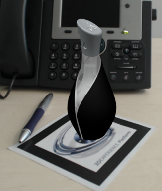
The exact position of the camera relative to the marker is retrieved and you can see the real-time capture of the object on your device. Below is an example of the result you can obtain:
- Click iV Magic Window
 to quit the command. to quit the command.
Calibrate the Camera
You can estimate the characteristics of a physical camera, especially its focal length and distortion parameters. Without a calibrated camera, it is not possible to make virtual 3D images accurately project on the real world.
-
To calibrate the camera, proceed as follows:
- If you already know the camera parameters (for instance if it has already been
calibrated), select Camera calibration file in the Camera
Calibration area. This option lets you select a text file containing the camera
calibration parameters. All parameters are stored in a single line as follows:
xsize ysize cc_x cc_y fc_x fc_y kc1 kc2 kc3 kc3 kc5 kc6
                iter
where:
- xsize, ysize: calibrated frame dimensions (does not have to match the frame
dimensions at runtime)
- cc_x, cc_y: principal point location (in pixels)
- fc_x, fc_y: focal length (in pixels)
- kc1..kc6: radial/tangential distortion coefficients (kc6 is currently not in
use)
- iter: number of iterations for distortion compensation
For example:
640 480 318.613463049990120 242.528511619033760 553.111326706724300
                  550.790645874873350 0.053851232286206 -0.196157056647373 -0.001007178693043
                  0.000594343958909 0.0 0.0 0.0
The file format used is compatible
with the ARToolkitPlus library. Below is the mapping between OpenCV and
ARToolkitPlus conventions:
| ARToolkitPlus |
OpenCV |
| xsize |
- |
| ysize |
- |
| cc_x |
cx |
| cc_y |
cy |
| fc_x |
fx |
| fc_y |
fy |
| kc1 |
k1 |
| kc2 |
k2 |
| kc3 |
p1 |
| kc4 |
p2 |
| kc5 |
k3 |
- Otherwise, select Interactive. This option lets you
compute the camera parameters using the Camera Calibration Wizard or the Automatic
Camera Calibration. You automatically retrieve the camera calibration parameters by
moving a calibration pattern in front of your camera.
This calibration technique
has been implemented in OpenCV (for more information, browse the following website:
http://opencv.org). If this option is selected, the AR
component detects the camera calibration pattern (the 11x4 array of dots by default)
in the images provided in the video source. You can calibrate:
- The current camera at the selected resolution.
- A camera which has been used to create a set of images containing the
calibration pattern. Note that:
- The sequence images must contain enough valid images with the calibration
pattern.
- All provided images are considered but they might not be usable (due to
lighting conditions, for instance).
- The more images, the better as long as they are distinct enough.
-
Print the calibration pattern (ideally, using a laser printer). This pattern is
provided as a .pdf file in
C:\Program Files\Dassault
          Systemes\B424\win_b64\resources\CameraCalibration\Pattern_ACircles_11x4_24mm.pdf
-
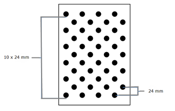
Measure the printed pattern to ensure its size has not been scaled by the
printer:
Note:
If you do not have a printer, you can display the pattern on a LCD
monitor or a mobile device but make sure the displayed pattern has the correct
physical size.
-
Glue the pattern on a rigid surface (such as a rigid cardboard, a piece of wood
or even better, glass) and make sure the pattern remains straight (there should be
no air bubbles between the paper and the pattern).
-
When the calibration pattern is ready, choose between calibrating the camera
using a live video feed, or provided image files.
- If you selected Live camera and Interactive, the Camera Calibration Wizard starts to help you calibrate your camera.
- If you are facing the camera, switch to Mirror rendering mode. Also make sure the action bar is minimized.
In this mode, color guides are displayed to help you position the calibration. Each color corresponds to an edge of the pattern in its target pose. - When the color guides appear, place the pattern in front of the camera until you see it surrounded by color edges.
Some white "rubber band" links can be seen between the corners of the pattern and those of the target pose.
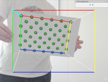
- Orient the pattern so that the links between the pattern and the pose do not cross. Do not orient the pattern upside down.
The aim is to make all these links as short as possible. When the corners of the current pose are close enough to those of the target, then the links turn Cyan and become thicker to indicate that the distance is considered as valid. - Make sure the approximate scale and orientation of the pattern are correct.
- Move closer or further away from the camera to make the corners of the current and target poses match as much as possible.
When the pose is successful, a snapshot is taken and a new target pose is displayed. Below are all the 11 target poses to obtain:
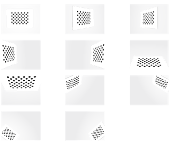
- Repeat the steps above to define the remaining target poses.
Whatever the calibration method, the screen blinks whenever a pattern is correctly detected. A furtive notification is also displayed to indicate the number of remaining poses. To take advantage of this feedback, it is recommended to leave the AR Configuration dialog box visible during the calibration process. When the calibration is over, the parameters are applied to the current view and a calibration file is generated in %TEMP%\CameraCalibration. This directory stores all files and snapshots related to camera calibration. The calibration file contains is named after the camera resolution and name with the *.cal extension, for instance CameraCalibration_Logitech_Webcam_C920-C_YUY2_640x480.cal.
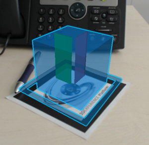
A wrong camera calibration leads to an incorrect projection of the virtual model:
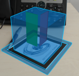
A correct camera calibration improves the projection and overlay of the virtual model on the marker:
|
 .
.
 to access configuration options.

 to start the camera.
 to quit the command.


