Using Clipping Tool | ||||||
|
| |||||
-
From the
Tools section of the
action bar,
click
Clipping Tool
 .
Note: You can also select the objects to clip before clicking the command.
.
Note: You can also select the objects to clip before clicking the command.Important: In Product Finder, the command is available only if the Activate Navigation Experience option available at Me  > Preferences > App Preferences > Social and Collaborative
> Global Design
Management > Product Finder > User
Interface is selected.
Also, the clipping tool is only supported by the In Place 3D layout type.
- If the command is launched without selecting any objects,
- In the single plane mode, a clipping plane is created, at the center of the bounding box.
- In the slice mode, all objects are covered by two clipping planes.
- In the box mode, a clipping box (defined by the bounding box), covering all objects is created.
For the single plane and slice modes, the clipping planes are placed normal to the x, y, or z axis, according to the preference set for the Normal direction option.
- If a single planar face is selected,
- In the single plane mode, a single clipping plane is created at the center of the selected planar face along the selected face.
- In the slice and the box modes, the position and the size of the clipping planes or the box is decided by the bounding box of all the selected elements.
- If any other type of selection is made,
- In the single plane mode, a clipping plane is created at the center of the bounding box.
- In the slice and the box modes, the position and the size of the clipping planes or the box are decided by the bounding box of all the selected elements.
- If the command is launched without selecting any objects,
-
Select a display plane mode on the
context toolbar
to define the type of the clipping ROI.
Following display plane modes are available:
Mode Description Display a plane 
Defines the clipping ROI using a single plane. 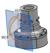
Display a slice 
Defines the clipping ROI using two parallel planes. 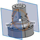
Display a box 
Defines the clipping ROI using a box. 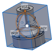
Display clipping volume using space 
Defines the clipping ROI using a space. For more information, see Clipping Using a Space.  By default, Display a plane mode
is selected.
The clipping boundaries are marked by the clipping planes depending upon the selected mode.
 -
Select one of the following clipping definition options from the
context toolbar:
Option Description Define clipping using objects selection (  ,
,
 ,
,
 )
)Lets you define the ROI by selecting the objects in the tree or in the 3D area. To validate the selection, click OK in the validation panel or press Enter. Define clipping using mouse rectangular trap (  ,
,
 )
)Lets you define the ROI by selecting the objects using the mouse trap selection. Reset Clipping (  ,
,
 ,
,
 )
)Lets you reset the ROI to the default size and position, covering all objects in the session. The position is same as if the command is launched without selecting any objects, depending on the selected clipping mode. Define Clipping using space list 
Lets you define the ROI by selecting a space. This option is only available for the slice and box modes. Note: This command is available only in Space Allocation. -
Select one of the following options from the
context toolbar
to control the clipping:
Option Description Activate Clipping 
Activates the clipping. 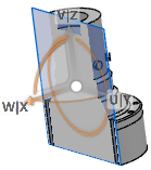
De-activate Clipping 
Deactivates the clipping. 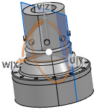
Display only the contour of the section 
Activates the clipping on both sides of the clipping plane to clip the objects completely. The contours are visible, irrespective of the contour options. 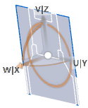
-
Right-click anywhere in the
3D area
and select
Properties.
In the Properties dialog box,
- Specify the clipping plane color and transparency.
- Select the Compute contour check box to activate the contours and
specify the color, line type, and thickness for them.
You can also select the Compute Contour check box in Me
 > Preferences > Common Preferences > 2D 3D View Display > Visualization > Clipping to activate the contours by default during the
clipping creation.
 These contours can be measured using the measure commands.
- Specify the color for capping.
The capping is visible when the contours are activated.
- Position the clipping as required. For more information, see Positioning the Clipping.
-
Right-click anywhere in the
3D area
and select
Cut/Uncut to control the objects to be
considered for clipping.
-
In the
Cut Elements dialog box, select
Cut selected elements
 or
Do not cut selected elements
 .
.
- Depending on the option selected, select the objects in the tree or in the 3D area.
- Optional: Select Clear all to clear the selection.
- Click OK.
The objects selected as the cut elements are considered for clipping. -
In the
Cut Elements dialog box, select
Cut selected elements
-
To validate the clipping, do one of the following:
- Click anywhere in the 3D area.
- Press Esc.
- Right-click anywhere in the 3D area and select Exit Clipping Edition.
- Optional:
To edit the clipping definition:
-
Do any one of the following:
- Right-click the clipped object or anywhere in the 3D area, and select Clipping > Edit Clipping.
- Click
Edit Clipping
 on the
action bar.
- If the contour is computed, select the contour and click
Edit Clipping
 on the
context toolbar.
Tip: You can also use Ctrl + Shift + V to edit the clipping. - Edit the clipping definition as required.
- Validate the clipping.
The options selected on the context toolbar are saved for the future clipping operation. -
Do any one of the following:
- Optional:
On the
action bar,
click the
Clipping Tool
 command again to turn it off.
You can also use Ctrl + Alt + K to toggle between activating and deactivating the Clipping Tool command.Note: When you use the clipping tool for GEOVIA block model data in the Plane clipping mode:
command again to turn it off.
You can also use Ctrl + Alt + K to toggle between activating and deactivating the Clipping Tool command.Note: When you use the clipping tool for GEOVIA block model data in the Plane clipping mode:- The blocks located on one side of the clipping plane are not clipped.
- The blocks located on other side are occluded.