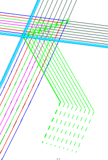
Creating Angle Cuts Manually

You can create angle cuts to support manufacturing constraints.

Note: This task is available in Composites Design.

See Also
Using the Grid Angle Cut Wizard
  1. From the Grid Design section of the action bar, click Grid Angle Cut .
  2. Pick the vertices to process.
    • Click to remove the selected vertex from the selection.
    • Click to propagate your selection to the next vertices downward.
    • For each selected vertex, the dialog box is updated with its index, the name of the ply it belongs to, and the name of its two ramp supports.
    • The vertices are highlighted in the work area.
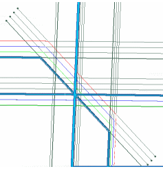
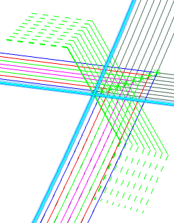
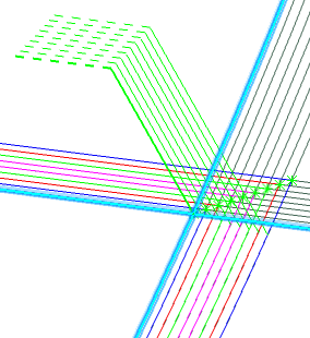
    • A preview of the result is displayed.

    Note: A display in red indicates that the result is not valid.
  3. Click Next under Side to switch to the next possible result.


    or

  4. Define the Fiber draping angle from its value or the direction of a selected element.
  5. Define the minimum tape length.

  6. Define extrapolation lengths (sufficient to cross all the plies that have an angle cut).

    Important: Pick the vertices in proper order.

  7. Under Slope, define the staggering.

    Once vertices are selected, Same as ramp support is replaced by the actual values

    • Either as Same as ramp support #1 (as found in first column Grid Ramp Support).
    • Or as Same as ramp support #2 (as found in second column Grid Ramp Support).
    • Or as an Other slope. When this option is selected, the Slope value parameters become available.
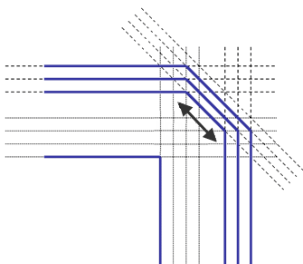
      • Step is the length between the angle cut edges.
      • Rate is the ratio that defines the slope.
      • Angle is the angle of the drop-off.
      • Material is the expected material thickness.
      See Creating Ramp Supports for more information.

A Grid Angle Cut Set is created.

Associated Ramp Definitions are created in a dedicated node, under the Ramp Definitions in Composites Parameters. The node is displayed according to the option specified in Preferences.

Note:

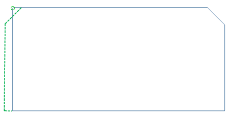
Only when creating the first angle cut, the ply is made bigger, possibly by adding material as shown below. The original ply is shown as the dotted line, the enlarged ply as the solid line, with the first angle cut.
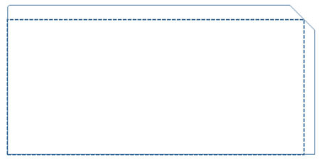
This is not repeated when creating another angle cut.

The circle represents the picked vertex, the dotted line the angle cut.