-
From the Grid Design section of the action bar, click Grid Angle Cut Init

-
Select the Panel.
-
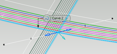
Define the extreme vertex of the angle cut as a point or as the intersection of two curves.
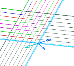
- Click one arrow in the 3D area, or Next to define on which side the plies are extended.
The current direction is highlighted.
- Define the Fiber draping angle from its value or the direction of a selected element.
- Define the minimum tape length.
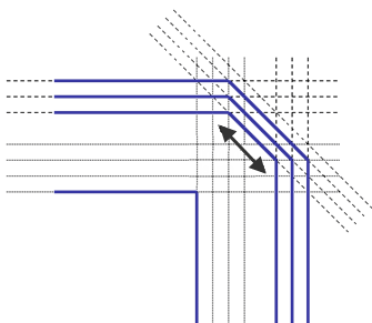
- Define extrapolation lengths (sufficient to cross all the plies that have an angle cut).
-
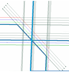
Click Preview to
verify the result.
A Grid Angle Cut Set is created.
Associated Ramp Definitions
are created in a dedicated node, under the Ramp Definitions in
Composites Parameters. The node is displayed according to the
option specified in Preferences.