Using the Material Addition Wizard | ||||
|
| |||
-
From the Skin Swapping and Ply Extensions section of the action bar, click Material Addition Wizard
 .
.
- Key in:
- Optional:
Select Turn off to minimize ply crossing.
- If Turn off is not selected, the lateral staggering is computed.
- If Turn off is selected, no lateral staggering is selected, only the
minimum cut length is taken into account.
 Note: Turning the lateral staggering off is different from setting it to 0:
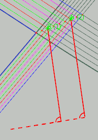
- If Turn off is not selected, the lateral staggering is computed.
-
Under Generation, select one shape to initialize the addition of
material:
 adds a rectangular shape to the ply, with a 90 degrees shape angle,
and a middle positioning (rectangle) for all vertices.
adds a rectangular shape to the ply, with a 90 degrees shape angle,
and a middle positioning (rectangle) for all vertices.
 adds a triangular shape to the ply, with a 90 degrees shape angle,
and first positioning (triangle) for all vertices.
adds a triangular shape to the ply, with a 90 degrees shape angle,
and first positioning (triangle) for all vertices.
 adds a triangular shape to the ply, with a normal edge back to contour, a shape angle that ensures a normal edge back, and first positioning (triangle) for all vertices.Note: The return angle may be more than 90 degrees.
-
If a better balance of material addition is required, select Force alternate side.
- If Force alternate side is not selected, the material is added always on
the same side.
- If Force alternate side is selected, the material is added on one side,
then on the other.

- If Force alternate side is not selected, the material is added always on
the same side.
-
Click Analyze.
The wizard:
- Finds all the ply contour vertices with discontinuities in tangency.
- Ignores those where the discontinuity is already the result of a material addition.
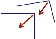
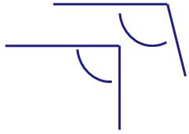
- Checks the angle between the tangents at the vertices and ignores the vertices
where this angle is too large.
- This angle is valid:
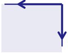
- This angle is invalid:

- This angle is valid:
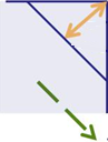
- Checks the angle between each tangent and the ply orientation (displayed in dash
green below) and ignores the vertices where this angle is lower than
Required angle between tangent and ply orientation, for
example
- This angle is valid:
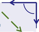
- This angle is invalid:
- This angle is valid:
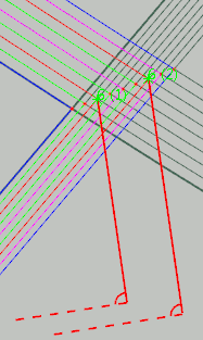
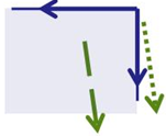
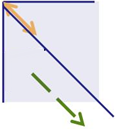
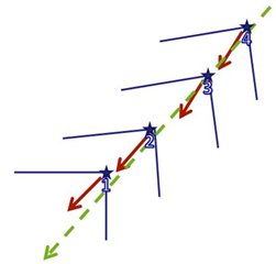
- Finds out whether a material addition is required or not: it computes an offset
from the vertex, equal to the tow width, parallel to the direction of the ply
orientation. A material addition is required if the length of this curve is smaller
than the Minimum length. In the examples below:
- The offset from the corner is shown by the orange double-headed arrow.
- The ply orientation is given by the dotted green arrow.
- The minimum length is visualized as the blue line.
- A material addition is required in this case.
- No material addition is required in this case.
- Ignores vertices where the ply orientation is not consistent with the
tangents.

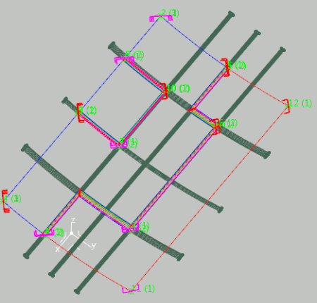
Then, the wizard groups the vertices
- Having the same ply orientation.
- Complying with the Maximum distance with closest vertex.
- Having almost the same bisector as the first vertex of the group.
- Having almost the same angle between tangents.
Within a given group, the vertices are ordered according to their abscissa along an average bisector.
are then previewed in the 3D area, with some (not all) possible modifications, based on the active Default usual shape.
- For any Default usual shape, right-click the preview and select the required menu item:
- Ignore vertex
- The vertex is removed from the group and no taken into account during the generation of the material addition.
- The lateral staggering is updated accordingly in the preview.
- Ignore group: The group is no taken into account during the generation of the material addition.
- , , let you change the usual shape used for the material addition.
- Other side: for a non-symmetrical usual shape, changes the side of all the material additions of the group.
- Ignore vertex

The material additions are created in the work area, under . They can be edited individually.